746-819-B0-001, Rev A (06/2017)
3
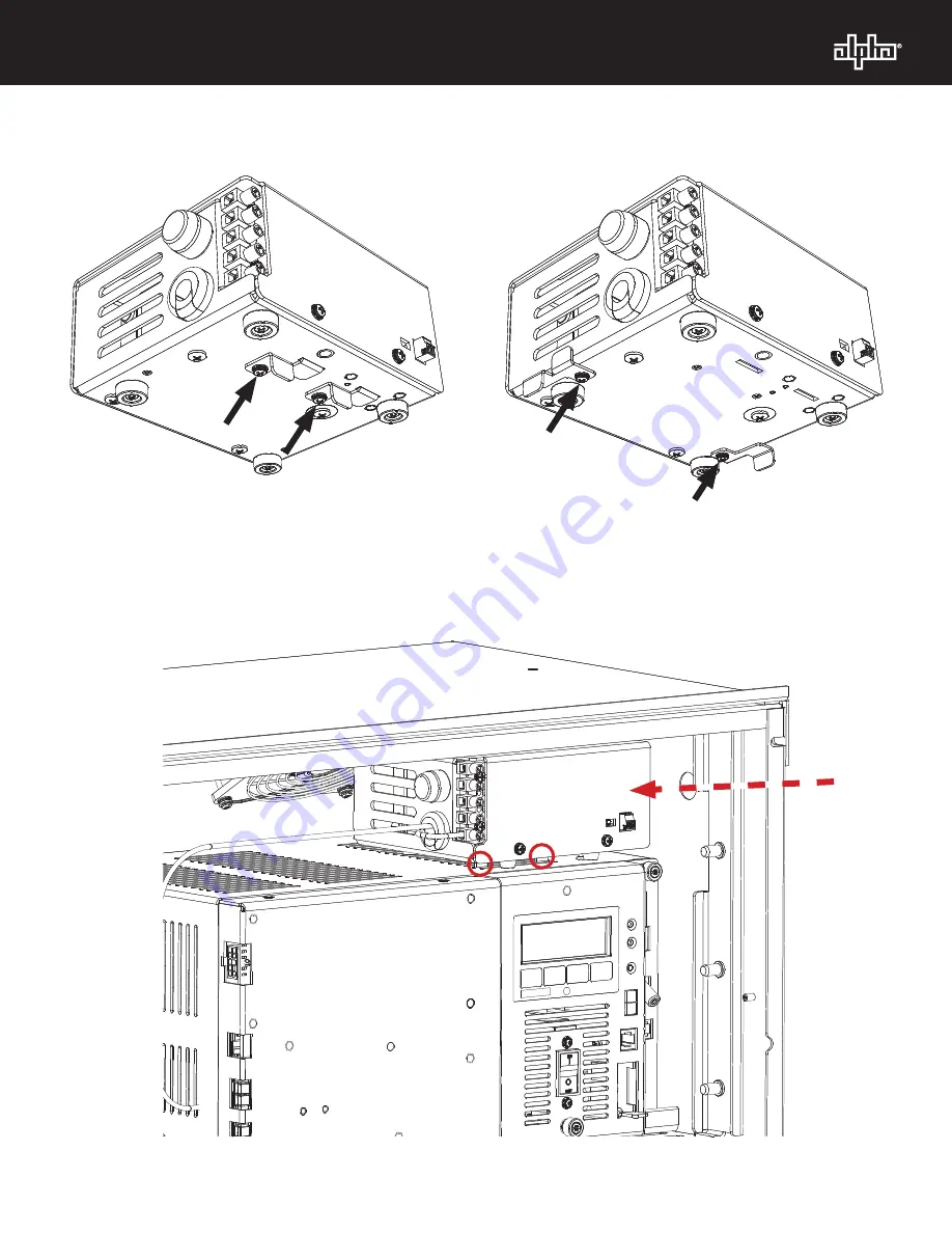
Fig. 3, Mounting Clips
–
XM3 Configuration
Fig. 4, Mounting Clips
XM2 Configuration
Fig. 5, XMP-8D Alternate Installation Location XM3
Страница 1: ...OUTPUT INPUT VOLTAGE TAP SELECT XMP 8D Layout 5 or 12VDC 11W Output 5 or 12VDC Select Switch AC Input Fuse 6 25A 250V Slow Blow Side View Front View Equipment powered by XMP 8D should be located outsi...
Страница 2: ...ue 2 With the front door of the PWE open install the XMP 8D on top of the power supply For an XM3 install the transformer above the inverter module allowing the mounting clips to slot into the vents o...
Страница 3: ...746 819 B0 001 Rev A 06 2017 3 Fig 3 Mounting Clips XM3 Configuration Fig 4 Mounting Clips XM2 Configuration Fig 5 XMP 8D Alternate Installation Location XM3...
Страница 4: ...4 746 819 B0 001 Rev A 06 2017 Fig 7 XMP 8D Alternate Installation Location XM2 Mounting Clip Fig 6 XMP 8D Alternate Installation Location XM2...
Страница 5: ...o match 2 Connect ground wire from XMP 8D to the cabinet ground stud 3 Make auxilary power connections if applicable This may include 5VDC or 12VDC Selection Terminal Connections 4 Install connected d...
Страница 6: ...63Hz AC Output Voltage 120VAC AC Output Power 250W AC Output Connection Terminal Block 12 Gauge Max DC Aux Output 5VDC 12VDC switchable DC Aux Output Power 11W DC Aux Output Voltage Ripple 250mV DC Au...