Alpha Alpha Top Easy-Flue 500 mm Скачать руководство пользователя страница 2

2

Alpha Top Easy-Flue

2. INSTALLATION INFORMATION

a.

Use the template (supplied with the boiler) to mark the flue position and cut a 130 mm diameter hole for the flue (use
a 127 mm core drill). This size of hole provides sufficient room for the flue to be fitted to the top of the boiler.
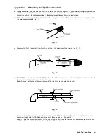
Note: If a 110 mm hole is cut for the flue, it is difficult to locate the flue onto the boiler flue adaptor, disconnect the duct
from the bend by removing the fixing screw. After installation ensure the duct is re-assembled onto the bend correctly.

Mount the boiler on the wall as described in the boiler Installation and Servicing instructions.

b.

Fit the flue terminal (supplied with the boiler) to the enlarged end of Duct 'B'. Secure with two screws supplied with
the terminal as shown in Fig. 3.

c.

Extend the telescopic flue to its full length. From the inside, pass the assembly through the wall. Seat the flue bend
onto the boiler flue adaptor.

d.

From outside, push the terminal in towards the wall until the screws securing the terminal are in line with the outside wall.
See Fig. 4.
Note: If there is no access to the outside wall, refer to Appendix 1.

e.

Carefully remove the flue assembly from the wall. Seal and secure the joint between the ducts with the sealing tape
supplied.

f.

Position the rubber seal over the 90° bend as shown in Fig. 5.

g.

Fit the inside flue sealing collar over the flue, see Fig. 5. From the inside, pass the flue assembly through the wall.

h.

Secure the 90° bend to the boiler using the clamp and rubber seal. Ensure that the seal covers the bend and adaptor
joint. See Fig. 6.

i.

Make good the inside and outside walls with the flue collars. See Fig. 6.
Note: The second flue collar is supplied with the boiler.

Fig. 3

Fig. 4

Fig. 5

Fig. 6

Содержание Alpha Top Easy-Flue 500 mm

Страница 1: ...g 1 and 2 b The Easy Flue includes a 90 bend no separate 90 bend is required c Ensure that there is a slight downward slope of the flue to outside d The flue system must be installed in accordance with BS 5440 1 1990 e The Easy Flue is suitable for use in the flue length ranges given in Fig 1 and 2 Fig 1 Rear Flue Fig 2 Side Flue Note Where the length is less than the minimum or more than the maxi...

Страница 2: ...shown in Fig 3 c Extend the telescopic flue to its full length From the inside pass the assembly through the wall Seat the flue bend onto the boiler flue adaptor d From outside push the terminal in towards the wall until the screws securing the terminal are in line with the outside wall See Fig 4 Note If there is no access to the outside wall refer to Appendix 1 e Carefully remove the flue assembl...

Страница 3: ...e terminal Push the flue assembly through the hole so that the collar completely passes through the wall Then pull back into the correct position See Fig 8 Alpha 240 280 Range Rear Flue L Wall thickness 230 mm Side Flue L Wall thickness distance between boiler and wall 265 mm Alpha 500E Rear Flue L Wall thickness 200 mm Side Flue to right L Wall thickness distance between boiler and wall 215 mm Si...

Страница 4: ...5 mm 240 mm and 430 mm 25 mm and 180 mm 240 mm N A 120 mm or less N A LH Side Flue Up to Max 3890 mm 3855 mm Alpha 750 flue extension Part No 1000320 is required to extend the range of the telescopic flue Refer to Appendix 3 for instructions on how to extend the flue Note A 130 mm flue hole 127 mm core drill is required in the wall Between 225 mm and 415 mm Within the standard telescopic range Les...

Страница 5: ...11 c Remove the Duct B assembly from Duct A by pulling in the direction of the arrows See Fig 12 Fig 11 d Fit a 750 flue extension Part No 1000320 to Ducts A and D using the clamps and seal supplied as shown in Fig 13 Connect any additional extension in the same way Note Ensure that the end of the outer duct with the two holes is connected to Duct A Fig 12 e Continue to add flue extensions until t...

Страница 6: ... the ducts together ensure that all engaging ducts have no burrs and are not distorted g When the telescopic section of the flue has been adjusted to the correct length seal and secure the joint with the sealing tape supplied See Fig 15 Important Note Ensure that the inner duct is connected securely throughout the flue assembly Fig 14 Fig 15 h Continue to fit the complete assembly to the boiler as...

Отзывы: