


16
5.1
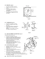
FILL THE SYSTEM
1.
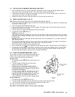
The boiler is fitted with an automatic air vent positioned on the pump (see Fig. 2 or 3). The vent is fitted with a non-sealing cap.
2.
Open the central heating flow and return valves (spindle flats in-line with valve) (see Fig. 11).
3.
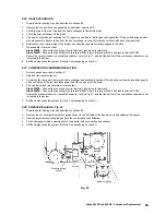
Open the fill point valve on the filling loop until water is heard to flow. To aid venting, the boiler drain point (see Fig. 35)
may be opened until water flows out. Close the drain point as soon as water appears.
4.
To remove the air - Vent each radiator in turn, starting with the lowest in the system.
5.
It is important that the pump is properly vented to avoid it running dry and damaging its bearings. Unscrew and remove the cap
from the centre of the pump. Using a suitable screwdriver rotate the exposed spindle about half a turn, then replace the cap.
6.
Check the operation of the pressure relief valve (see Fig. 35) by turning the head anti-clockwise until it clicks. The click is
the valve lifting off its seat allowing water to escape from the system - check that this is actually happening.
7.
Continue to fill the system until the pressure gauge indicates 1.0 bar. Close the fill point valve and check the system for
water soundness, rectifying where necessary. Disconnect the filling loop from the mains supply.
Water may be released from the system by manually operating the drain point (see Fig. 35) until the system design
pressure is obtained. The system design pressure (cold) should be between 0.75 and 1.25 bar.
Refer to sections 3.7 and 3.8. System volume and Filling the system.
8.
Open the mains water inlet valve (see Fig. 11). Turn on all hot water taps and allow water to flow until no air is present.
Turn off taps.
5.2
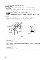
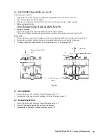
BOILER CONTROLS - Fig. 16
5
COMMISSIONING
Alpha 240XP and 240XE - Commissioning
Fig. 16
Alpha 240XP
Alpha 240XE
Gas
Control
GAS
OFF
System
Pressure
Gauge
Central
Heating
Thermostat
Domestic
Hot Water
Thermostat
Selector
Switch
Pilot and Burner Viewing Window
0
THERMOSTAT
0
THERMOSTAT
SELECTOR
bar
0
4
3
2
1
Clock
(if fitted)
OCEAN
240
XP
HELPLINE (OI322) 669443
QUOTE SERIAL NO. (SEE UNDER BOILER)
TO SET HEATING CLOCK (Mechanical)
Push tappets out for heating ON and IN for heating OFF. Set correct time
by turning 24hr dial. Manual switch to left - permanent OFF.,
middle - heating as tappets, right - permanent ON.
(If in doubt, see User Instructions).
PRESSURE GAUGE
When the boiler is cold the needle should be in green band.
To increase pressure connect filling loop under boiler.
Open valves. Close when needle is in green band.
Disconnect loop. (Contact your installer if in doubt).
TO LIGHT
Press in gas knob
for 60 seconds then release.
Warning: If pilot does not light or goes out wait at least
3 minutes. Then repeat.
Reset
Button
System
Pressure
Gauge
Central
Heating
Thermostat
Domestic
Hot Water
Thermostat
Selector
Switch
Burner Viewing Window
0
THERMOSTAT
0
THERMOSTAT
0
SELECTOR
bar
0
4
3
2
1
Clock
(if fitted)
RESET
OCEAN
240
XE
HELPLINE (OI322) 669443
QUOTE SERIAL NO. (SEE UNDER BOILER)
TO SET HEATING CLOCK (Mechanical)
Push tappets out for heating ON and IN for heating OFF. Set correct time
by turning 24hr dial. Manual switch to left - permanent OFF.,
middle - heating as tappets, right - permanent ON.
(If in doubt, see User Instructions).
PRESSURE GAUGE
When the boiler is cold the needle should be in green band.
To increase pressure connect filling loop under boiler.
Open valves. Close when needle is in green band.
Disconnect loop. (Contact your installer if in doubt).
Содержание Alpha 240XE
Страница 34: ...34 Alpha 240XP and 240XE Wiring Diagrams 9 WIRING DIAGRAMS 9 1 ILLUSTRATED WIRING DIAGRAM Alpha 240XP ...
Страница 35: ...35 Alpha 240XP and 240XE Wiring Diagrams 9 2 ILLUSTRATED WIRING DIAGRAM Alpha 240XE ...
Страница 36: ...36 Alpha 240XP and 240XE Wiring Diagrams 9 3 FUNCTIONAL FLOW WIRING DIAGRAM Alpha 240XP ...
Страница 37: ...37 Alpha 240XP and 240XE Wiring Diagrams 9 4 FUNCTIONAL FLOW WIRING DIAGRAM Alpha 240XE ...


