background image

Dear Customer,

Before you use the laser spirit level for the first time,
please read the instructions and observe the notes
on operation.
Ensure that these instructions are always kept next
to the unit.

1. Items supplied


1 laser spirit level


1 plastic case


1 90° angle attachment


1 line attachment


1 leveling base


1 tripod


2 batteries 1.5 V Micro (AAA) 

2. Technical data


Laser class

2


Laser wavelength

630 - 670 nm


Laser output

1 mW


Measuring range

ca. 50 m


Power supply 

2 x 1.5 V Micro (AAA)

Caution!
Laser radiation
Do not look into the beam
Laser class 2

2. Safety information

Protect yourself and the environment from accident
risks by taking the appropriate precautionary
measures.


Do not look directly into the laser beam with the
naked eye.


Never look directly into the ray passage.


Never direct the laser beam toward reflecting
surfaces, or persons or animals. Even a low
output laser beam can inflict injury upon the eye.


Important:

Using operating or adjusting devices

other than those specified here or using
alternative procedures can result in dangerous
exposure to radiation. 


Never open the spirit level or laser module.


When the spirit level is not going to be used for
an extended period of time, the batteries should
be removed.

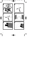
3. Illustration (Fig. 1)

Item

Description

1

ON/OFF button; battery compartment cover

2

Laser beam outlet hole

3

Leveling plate

4

Locking screw for leveling plate

5

Locking screw for clamp

6

Adjusting screws for leveling plate

7 Point 

level

4.  Assembly and adjustment 

(Figs. 1 + 2)

Place the tripod on a level surface. The telescoping
legs of the tripod can be adjusted to compensate for
any unevenness. Level the tripod using the point
level on the head of the tripod.

Screw the leveling plate on the tripod. Adjust the
leveling plate to horizontal position with the 3
adjusting screws (6) and the built-in point (7) level.

Attach the spirit level to the leveling plate with the
clamping screw (5). Adjust the spirit level to
horizontal position with the adjusting screws (6). The
air bubble in the level must stop exactly between the
two markings.

Slacken the locking screw (4) so that the upper
section of the leveling plate can be turned.

Turn the spirit level with the leveling plate through to
90°. Using the adjusting screws (6), adjust the level
of the spirit level to the point where it is exactly
horizontal.

Turn the spirit level with the leveling plate back to the
starting position. A minor readjustment may be
necessary.

You can precisely set the angle of rotation using the
graded scale on the leveling base. When the spirit
level is turned with the leveling plate, the laser beam
always remains at the same height.

GB

5

Anleitung LW 400 AlphaTools  20.01.2005  10:17 Uhr  Seite 5

Содержание 22.700.03

Страница 1: ... Niveau au laser Betjeningsvejledning laser lodstok Bruksanvisning Laser vattenpass Käyttöohje Laser vesivaaka Használati utasítás Lézer vízmérték Návod k obsluze Laserová vodováha Navodila za uporabo Laserska vodna tehtnica Naputak za uporabu Laserska libela LW 400 Anleitung LW 400 AlphaTools 20 01 2005 10 17 Uhr Seite 1 ...

Страница 2: ...2 1 4 5 6 2 3 Anleitung LW 400 AlphaTools 20 01 2005 10 17 Uhr Seite 2 ...

Страница 3: ...lter Batteriefach Abdeckung 2 Austrittsöffung Laserstrahl 3 Nivellierteller 4 Feststellschraube Nivellierteller 5 Feststellschraube Klemmbügel 6 Justierschraube Nivellierteller 7 Punktlibelle 4 Montage und Justierung Bild 1 2 Stellen Sie das Stativ auf eine ebene Fläche Unebenheiten können mit den Teleskop Füssen des Stativs ausgeglichen werden Richten Sie das Stativ mittels der am Stativkopf ange...

Страница 4: ...on 10 m 6 Verwendung der Aufsätze Verwendung Winkelaufsatz Bild 5 Stecken Sie den Winkelaufsatz direkt in die Strahl austrittsöffnung des Lasermodules Der austretende Laserstrahl wird um 90 umgelenkt Dadurch wird eine rechtwinkelige Bezugsebene zur Wasserwaage hergestellt Verwendung Linienaufsatz Bild 6 Stecken Sie den Linienaufsatz direkt in die Strahl austrittsöffnung des Lasermodules Durch den ...

Страница 5: ...Fig 1 Item Description 1 ON OFF button battery compartment cover 2 Laser beam outlet hole 3 Leveling plate 4 Locking screw for leveling plate 5 Locking screw for clamp 6 Adjusting screws for leveling plate 7 Point level 4 Assembly and adjustment Figs 1 2 Place the tripod on a level surface The telescoping legs of the tripod can be adjusted to compensate for any unevenness Level the tripod using th...

Страница 6: ...m 6 Using the attachments Using the angle attachment Fig 5 Insert the angle attachment directly into the outlet hole of the laser module The emerging laser beam will now be deflected by 90 creating a right angled reference plane to the spirit level Using the line attachment Fig 6 Insert the line attachment directly into the outlet hole of the laser module The line attachment projects a line on the...

Страница 7: ...ion 1 Interrupteur Marche Arrêt Couvercle du compartiment à piles 2 Orifice de sortie du rayon laser 3 Plateau de nivellement 4 Vis de fixation du plateau de nivellement 5 Vis de fixation de l étrier de serrage 6 Vis d ajustage du plateau de nivellement 7 Niveau à bulle 4 Montage et ajustement figure 1 2 Placez le trépied sur une surface plane Les inégalités peuvent être compensées à l aide des pi...

Страница 8: ...le Application du Sauterelle verticale 90 figure 5 Enfichez le sauterelle verticale 90 déviateur directement dans l orifice de sortie du rayon du module laser Le rayon laser sortant sera dévié de 90 Un niveau de référence carré est ainsi créé par rapport au niveau au laser Application du Sauterelle horizontale figure 6 Enfichez le sauterelle horizontale directement dans l orifice de sortie du rayo...

Страница 9: ...teringsskrue nivelleringsskive 7 Punktlibelle 4 Samling og indstilling fig 1 2 Stil stativet på en plan flade Ujævnheder kan udlignes med stativets teleskopfødder Ret stativet ind ved hjælp af punktlibellen som sidder på stativets hoved Skru nivelleringsskiven på stativet Juster nivelleringsskiven ind i horisontal position med de 3 justerskruer 6 og den indbyggede punktlibelle 7 Fastgør lodstokken...

Страница 10: ...erenceniveau til lodstokken Brug af liniepåsats fig 6 Sæt liniepåsatsen direkte ind i lasermodulets stråleudgang Med liniepåsatsen projekteres en linie ind på den væg som ligger over for stråleudgangen Marker først to punkter på væggen ved hjælp af laserstrålen Sæt liniepåsatsen ind i stråleudgangen og forbind den projicerede linie med de to markerede punkter ved at dreje påsatsen Spredningen af l...

Страница 11: ...uv nivelleringsunderlag 5 Låsskruv klämbygel 6 Justerskruv nivelleringsunderlag 7 Punktlibell 4 Montera och justera bild 1 2 Ställ stativet på en jämn yta Ev ojämnheter kan du kompensera genom att du ställer in stativets ben Justera in stativet enligt punktlibellen som finns i stativets övre del Skruva fast nivellerungsunderlaget på stativet Justera in nivelleringsunderlaget i horisontalt läge med...

Страница 12: ... lasermodulen Laserstrålen vinklas med 90 På så sätt har du fått en rätvinklig referensyta gentemot vattenpasset Använda Linjetillbehör bild 6 Sätt in Linjetillbehör direkt i laserstrålens utgångsöppning på lasermodulen Linjetillbehör projicerar en linje på väggen som finns mittemot laserstrålens utgångsöppning Utgå från laserstrålen och markera två punkter på väggen Sätt in Linjetillbehör i utgån...

Страница 13: ...nnekaaren lukitusruuvi 6 Vaaituslevyn säätöruuvi 7 Pistetasain 4 Asennus ja kohdistus kuvat 1 2 Aseta jalusta tasaiselle pinnalle Voit korjata epätasaisuudet jalustan teleskooppijalkojen avulla Vaaita jalusta vaakatasoon jalustan päähän asennetun pistetasaimen avulla Ruuvaa vaaituslevy jalustalle Kohdista vaaituslevy vaakasuoraan asentoon 3 säätöruuvin 6 ja laitteeseen asennetun pistetasaimen avul...

Страница 14: ...en luodaan vesivaa alle suorassa kulmassa oleva viitetaso viivatuki kuva 6 Työnnä viivatuki suoraan lasermoduulin säteen ulostuloaukkoon viivatuki projisoidaan viiva ulostuloaukkoa vastapäätä olevalle seinälle Merkitse ensin lasersäteen avulla kaksi pistettä seinään Työnnä viivatuki säteen ulostuloaukkoon ja yhdistä projisoitu viiva molempiin merkittyihin pisteisiin kääntämällä viivatuki Lasersäte...

Страница 15: ... 3 Ábra 1 es kép Poz Megnevezés 1 Ki bekapcsoló elemrekesz fedél 2 Lézeroptika nyílása 3 Szintezôtányér 4 Rögzítôcsavar a szintezôtányérhoz 5 Rögzítôcsavar a csíptetôfülhöz 6 Beállítócsavar a szintezôtányérhoz 7 Pontlibella 4 Felszerelés és beállítás 1 es 2 es kép Állítsa az állványt egy sík felületre Egyenletlenségeket az állvány teleszkópos lábai segítségével ki lehet egyenlíteni Igazítsa be az ...

Страница 16: ...lsághoz viszonyítva 90 os szöglettoldat 5 es kép Tegye a 90 os szöglettoldat közvetlenül a lézermodul lézeroptika nyílásába A kilépô lézersugár elhajlása pontosan 90 ban történik Ezáltal egy derékszögû vonatkozási síkot lehet létrehozni A Vonalazási toldat 6 ös kép Tegye a Vonalazási toldat közvetlenül a lézermodul lézeroptika nyílásába A Vonalazási toldat által az optika nyílásával szeben lévõ fa...

Страница 17: ...cí šroub nivelačního talíře 5 Stavěcí šroub svěracího třmenu 6 Justovací šroub nivelačního talíře 7 Bodová libela 4 Montáž a justování obr 1 2 Postavte stativ na rovnou plochu Nerovnosti mohou být vyrovnány teleskopickými nožkami stativu Vyrovnejte stativ pomocí bodové libely upevněné na hlavě stativu Našroubujte nivelační talíř na stativ Justujte nivelační talíř v horizontální poloze pomocí 3 jus...

Страница 18: ...erový paprsek je odchýlen přesně o 90 Tím je vytvořena pravoúhlá vztažná rovina k vodováze Použití přimkový nástavec obr 6 Zasuňte přimkový nástavec přímo do otvoru výstupu laserového paprsku laserového modulu Pomocí přimkový nástavec je na zed ležící oproti otvoru výstupu promítnuta čára Nejdříve pomocí laserového paprsku označte dva body na zdi Zasuňte přimkový nástavec do otvoru pro výstup papr...

Страница 19: ...ka 1 Stikalo za vklop izklop pokrov prostora za baterije 2 Izstopna odprtina za laserski žarek 3 Nivelirni krožnik 4 Pritrdilni vijak nivelirnega krožnika 5 Pritrdilni vijak spnejalna ročica 6 Nastavitveni vijak nivelirnega krožnika 7 Točkovna libela 4 Montaža in nastavljanje Slika 1 2 Postavite stativ na ravno podlago Neravnine lahko poravnate s teleskopskimi nogami stativa Izravnajte stativ s po...

Страница 20: ...5 Vstavite kotni nastavek 90 direktno v odpirtino za izstop laserskega žarka na laserskem modulu Izstopajoči laserski žarek se bo odklonil za natančno 90 Na ta način vzpostavite pravokotni refernčni nivo glede na vodno tehtnico Uporaba linijski nastavek Slika 6 Vstavite linijski nastavek direktno v odprtino za izstop laserskega žarka na laserskem modulu S pomočjo linijski nastavek se bo projiciral...

Страница 21: ...Naziv 1 prekidač poklopac baterija 2 izlazni otvor laserske zrake 3 tanjur za niveliranje 4 vijak za fiksiranje tanjura za niveliranje 5 stezni vijak 6 vijak za justiranje tanjura za niveliranje 7 točkasta libela 4 Montaža i justiranje slike 1 2 Postavite stalak na ravnu površinu Neravnine se mogu izravnati pomoću teleskopskih nogu stalka Izravnajte stalak pomoću točkaste libele koja se nalazi na ...

Страница 22: ...i najviše 5 mm važi za udaljenost od 10 m Uporaba Kutni nastavak 90 slika 5 Stavite Kutni nastavak 90 direktno u izlazni otvor zrake u laserskoj jedinici Laserska zraka koja izlazi se skreće za točno 90 Time se stvara pravokutna referentna ravnina u odnosu na libelu Uporaba Linijski nastavak slika 6 Stavite Linijski nastavak direktno u izlazni otvor zrake u laserskoj jedinici Kroz Linijski nastava...

Страница 23: ...oopan unionin direkti ivien ja normien mukaista yhdenmukaisuutta tuotteelle N erklærer herved følgende samsvar med EU direktiv og standarder for artikkel заявляет о соответствии товара следующим директивам и нормам EC izjavljuje sljedeću uskladjenost s odredbama i normama EU za artikl declarå urmåtoarea conformitate cu linia direc toare CE µi normele valabile pentru articolul ürün ile ilgili olara...

Страница 24: ...ítésének a feltétele a készülékünknek a használati utasításnak megfelelô szabályszerě karbantartása úgymint rendeltetészerěi használata Magától értetôdô hogy ez a 5 év alatt a törvény szerinti szavatossági jogai fennmaradnak A jótállás a Németországi Szövetségi Köztársaság területére érvényes vagy a regionális fô forgalmazó partner országaiban kiegészítésként a helyi érvényes törvényi elôírásokhoz...

Страница 25: ...lavního distribučního partnera jako doplněk lokálně platných zákonných předpisů V případě potřeby se prosím obrat te na Vašeho kontaktního partnera regionálního příslušného zákaznického servisu nebo na dole uvedenou servisní adresu GARANCIJSKI LIST Za napravo ki je navedena v navodilih dajemo 5 leti garancije v primeru če bi bil naš proizvod pomanjkljiv 5 letni rok začne teči s prenosom jamstva al...

Страница 26: ...ative to returning the electrical device the owner is obliged to cooperate in ensuring that the device is properly recycled if ownership is relinquished This can also be done by handing over the used device to a returns center which will dispose of it in accordance with national commercial and industrial waste management legislation This does not apply to the accessories and auxiliary equipment wi...

Страница 27: ...rs syfte har varit att komplettera den förbrukade utrustningen Koskee ainoastaan EU jäsenmaita Älä heitä sähkötyökaluja kotitalousjätteisiin Sähkökäyttöisiä ja elektronisia vanhoja laitteita koskevan Euroopan direktiivin 2002 96 EY mukaan joka on sisällytetty kansallisiin lakeihin tulee loppuun käytetyt sähkökäyttöiset työkalut kerätä erikseen ja toimittaa ympäristöystävälliseen kierrätykseen uusi...

Страница 28: ...pět povinen ke spolupráci při odborné recyklaci v případě že se rozhodne přístroj zlikvidovat Starý přístroj může být v tomto případě také odevzdán do sběrny která provede likvidaci ve smyslu národního zákona o hospodářském koloběhu a zákona o odpadech Toto neplatí pro ke starým přístrojům přiložené části příslušenství a pomocné prostředky bez elektrických součástí Der Nachdruck oder sonstige Verv...

Отзывы: