010-619-J0 Rev B
Page 34
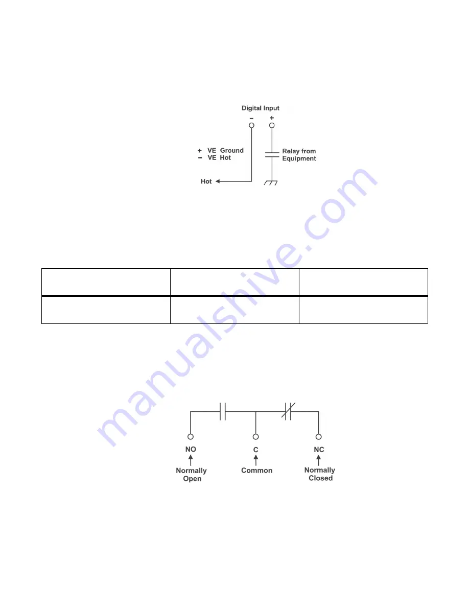
(dry contact – usually located on the equipment requiring monitoring). This method allows the digital
input to receive (or not receive) a Ground signal on an alarm.
Figure 25:
Digital Input Connection Method
Programming the Digital Input
The digital input channels can be programmed for “active high” or “active low. Active high indicates,
“alarm on the presence of a ground signal” and active low indicates, “alarm on the removal of a ground
signal.” See controller software manual for detailed instruction on programming.
NOTE
:
Between 1.5 to 5V is an undefined operation.
6.9.3
Alarm (Relay) Outputs
Terminals provide contacts for extending various alarm or control signals. Each relay output (K2, K3,
K4) can be wired for NO or NC operation during an alarm or control condition.
Figure 26:
Relay Connections
Relays can be programmed to energize or de-energize during an alarm condition (see controller soft-
ware manual). When the CXCM1 reset button is pressed or power is lost, all relays de-energize.
These relays could be used for additional external LVD contactor control; however, this would not
provide the redundant LVD control as with the assigned output pins described below.
Table 3:
Voltage Level Definitions for Digital Inputs
Voltage Range (Vdc)
Voltage Level (Vdc) Considered
As “0” (Off)
Voltage Level (Vdc) Considered
As “1” (On)
0-60
(System Voltage Setting)
-1.5 to 1.5V
-60 to -5V or +5 to +60V
Содержание Cordex HP 48 1.2kW
Страница 2: ......
Страница 4: ......
Страница 10: ...vi...
Страница 14: ...010 619 J0 Rev B Page 4...
Страница 16: ...010 619 J0 Rev B Page 6 Figure 1 Single Shelf Figure 2 Dual Shelf Figure 3 2RU Shelf...
Страница 28: ...010 619 J0 Rev B Page 18...
Страница 30: ...010 619 J0 Rev B Page 20...
Страница 46: ...010 619 J0 Rev B Page 36...
Страница 56: ...010 619 J0 Rev B Page 46...
Страница 58: ...010 619 J0 Rev B Page 48...


