SNX-60x0-486F Series Data Center Switch
Quick Installation Guide
2
Introduction
This guide is to assist the reader with the most basic
form of installation and connection to switches in
this series. As there is more than one switch in this
series, the diagrams might slightly differ, however,
the installation and connection is the same for all
switches in this series.
Package Contents
After purchasing any of the switches in this series,
the following items will be included in the package:
One SNX-60x0-486F Series Switch (This includes 1
power supply module and 3 fan modules).
One Quick Installation Guide.
One AC power cord.
One RS-232-to-RJ45 console cable.
One USB-to-USB console cable.
One pair of frontal rack-mount brackets.
One pair of rack-mount slider brackets.
Four rubber feet with adhesive patches.
Eight Phillips-head frontal rack-mount bracket screws.
One warranty card.
Note:
If any of the above mention items was not
found inside the package contents of this switch or
are damaged in any way, contact your reseller
immediately.
Hardware Installation
Installation Guidelines
This section will discuss the hardware installation
guidelines that administrators must follow in order
to properly and safely install this switch into the
appropriate environment.
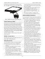
Installation using the Rubber Feet
When installing the switch in an area other than
inside a switch rack, like on a desktop, rubber feet
can be attached to the bottom panel of the switch.
On the bottom panel of the switch, there are clearly
marked squares where the rubber feet can be
attached. These marked squares are usually found
close to the corners of the switch’s bottom panel.
Adhesive material is included on the rubber feet.
Simply pull away the protective sticker, of each
rubber foot and then attach the foot into the
appropriately marked square. The rubber feet
cushion the switch, protecting the casing from
scratches and preventing it from scratching other
surfaces.
Figure 1 - Installation using the rubber feet
Install the switch on a sturdy, level surface that can
support the weight of the switch. Do not place any
heavy objects on the switch. Make sure that there is
proper heat dissipation from and adequate
ventilation around the switch. Leave at least 10 cm
(4 inches) of space at the front and rear of the
switch for ventilation.
Installation into a Rack
Normally, ToR switches are installed not only into a
rack-mount unit but at the top of the rack. The
switch can be mounted in a standard 19"(1U) rack
using the provided mounting brackets. The
following section will explain how to install the rack-
mount brackets onto the switch and then mount the
switch into a standard 1U rack-mount unit.
The following parts will be used to install the switch
into a rack-mount unit:
One pair of frontal rack-mount brackets.
One pair of rack-mount slider brackets.
Eight Phillips-head frontal rack-mount bracket screws.
Additional equipment needed to install the switch
into a rack-mount unit:
One Phillips-head screwdriver. This screwdriver will be
used for the rack-mount bracket screws
One additional screwdriver. This screwdriver will be
used for the rack-mount unit screws and its type and
size depends on the rack-mount unit screws being
used.
Eight rack-mount unit screws. These screws will be used
to attach the switch onto to the rack-mount unit and
are not included in the switch’s packaging as rack-
mount units differ at each installation site.


