background image

Operation

12

(06/2016)

Operation

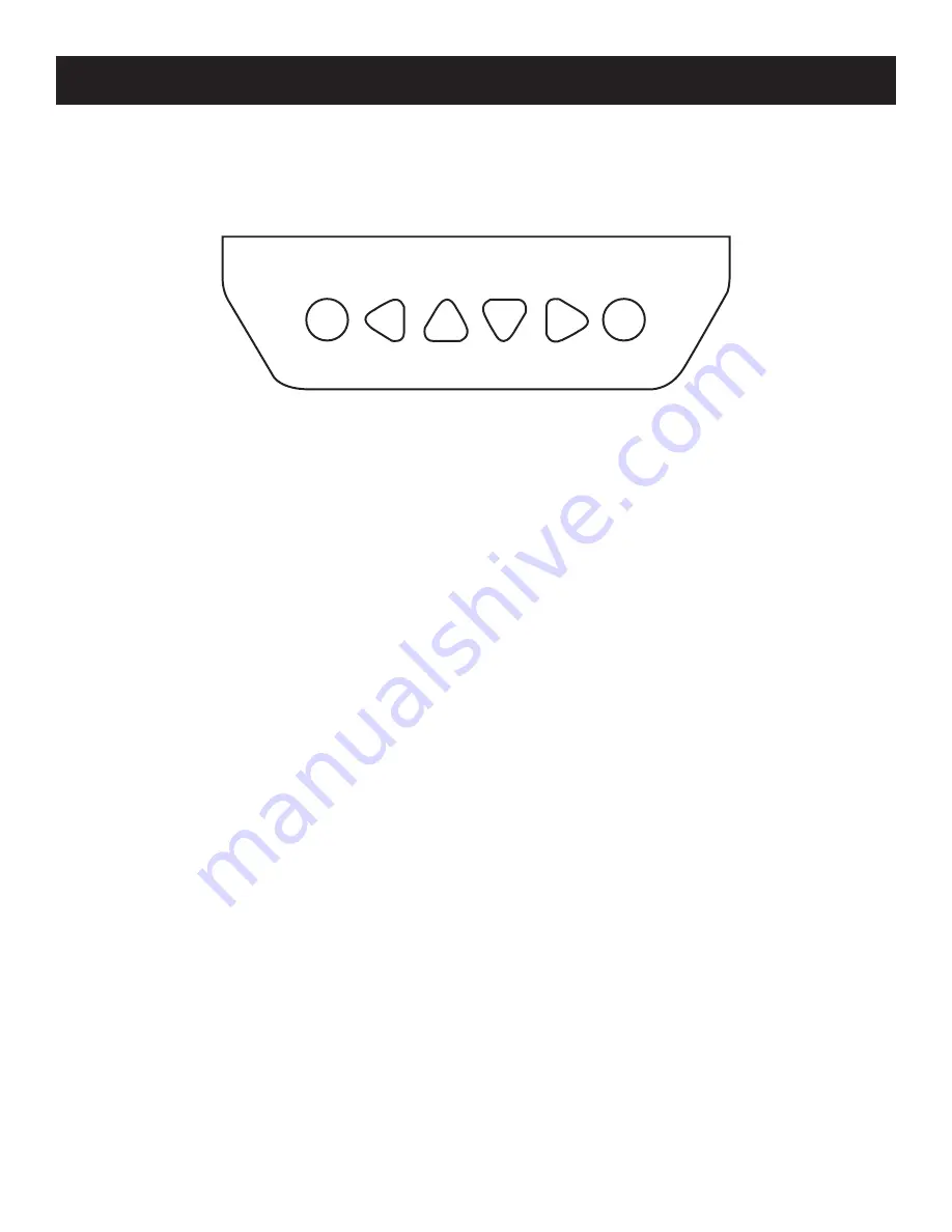
Buttons

Figure 8, Outback Mate Micro Buttons

From left-to-right, the buttons are: Esc, Left, Up, Down, Right, and OK. Pressing OK will navigate to a subpage, and pressing Esc will 

take the user back to the previous page. 

The default page is the “Browse” mode. Pressing OK and inputting the correct password will allow the user to enter “Modification” 

mode. The left and right buttons are used to move the cursor, while the up and down buttons are used to modify parameters. 

When modifying parameters, OK can be used to confirm the modification, while Esc can be used to cancel the modification.

Main Menu

The Main Menu is accessed by pressing Esc. On the Main Menu, the up and down buttons are used to move the cursor up and 

down the menu items. The screen displays 4 list items at a time. Press OK to select a subpage any of the listed subpages:

1.  Monitoring
2.  Device Info.
3.  Test Operation
4.  Control Para.
5.  Load Set
6.  Device Para
7.  Device PSW.
8.  Factory Reset
9.  Failure Info.
10.  Meter Para.

Esc

OK

Содержание OutBack Power Mate Micro

Страница 1: ...OutBack Mate Micro User s Manual Warning MATE MICRO COM Esc OK ...

Страница 2: ...OSS OR DAMAGE WHETHER DIRECT INDIRECT CONSEQUENTIAL OR INCIDENTAL WHICH MIGHT ARISE OUT OF THE USE OF SUCH INFORMATION THE USE OF ANY SUCH INFORMATION WILL BE ENTIRELY AT THE USER S RISK Notice of Copyright OutBack Mate Micro User s Manual October 2015 by OutBack Power Technologies All Rights Reserved Trademark OutBack Power and the OutBack Power logo are trademarks owned and used by OutBack Power...

Страница 3: ...nitoring Screen 11 Operation 12 Buttons 12 Main Menu 12 Real Time Monitoring 13 Device Information 15 Test Operation 15 Control Parameters 16 Battery Voltage Parameters 17 Load Setting 18 Device Parameter 20 Device Password 21 Factory Reset 21 Failure Information 22 Meter Parameter 23 Technical Specifications 24 Communication Cable Specifications 24 ...

Страница 4: ...unting 8 Figure 3 OutBack Mate Micro Mounting 8 Figure 4 Surface Mounting the OutBack Mate Micro 9 Figure 5 Front Overview 10 Figure 6 Rear Overview 10 Figure 7 Monitoring Screen Overview 11 Figure 8 Outback Mate Micro Buttons 12 Figure 9 Monitoring Screens 13 Figure 9 Monitoring Screens continued 14 Figure 10 Device Information Screen 15 Figure 11 Test Operation Screen 15 Figure 12 Control Parame...

Страница 5: ...ollow these instructions could result in sever shock or possible electrocution Use extreme caution at all times to prevent accidents Inspect the OutBack Mate Micro thoroughly If there is any damage to the OutBack Mate Micro notify the shipping company and OutBack Power immediately Read all instructions and cautionary markings prior to installation Keep the OutBack Mate Micro away from rain exposur...

Страница 6: ...es include Automatic identification and display of the type model and relevant parameters of the charge controller Real time display of operational data and working status of the connected devices in digital graphic and textual forms on a large multifunctional LCD screen Six navigation function keys Data and power flow on the same lead eliminating the need for external power Real time data monitor...

Страница 7: ...r M4x8 Pan Head Screws Four M4 Nuts Four Screw Plugs Phillips Screwdriver Table 1 Mounting Information See the following two sections for each mounting method Frame Mount Figure 1 Frame Mount Dimensions in mm Mounting Information Mechanical Parameter Parameter Overall Dimension in mm 4 49 x 4 49 x 1 90 114 x 114 x 48 2 Mounting Dimension in mm 3 31 x 3 31 84 x 84 Terminal ф4 3 84mm 84mm 114mm 48 2...

Страница 8: ...on of the base and erect the plastic expansion bolts 2 Use four ST4 2x32 self tapping screws to fix the frame Figure 2 Frame Mounting 3 Use four M4x8 pan head screws to mount the OutBack Mate Micro to the frame Figure 3 OutBack Mate Micro Mounting 4 Affix the four screw plugs to the screw holes ...

Страница 9: ...four M4x8 pan head screws with M4 nuts to mount the OutBack Mate Micro onto the surface 3 Affix the four screw plugs to the screw holes Figure 4 Surface Mounting the OutBack Mate Micro Prior to installation consider the amount of space required to plug unplug the communication cable as well as the length of the cable Notice ...

Страница 10: ...es the communication status between the OutBack Mate Micro and the OutBack FLEXmax Charge Controller Display Screen LCD operational interface Buttons Four navigational buttons up down left and right and two operational but tons OK and Esc RS485 Communication and Power Interface Communication and power supply cable interfaces used for a communications connection with the controller Figure 5 Front O...

Страница 11: ...tage and Current Values Battery Icon 17 5V 13 8V 13 8V 15 2A 5 2A 10 0A Monitoring Screen Icons Day and Night Icons Night Day The threshold voltage is 1V Higher than 1V is daytime Charge Current Icon The charge current icon will be static if there is no activity and dynamic if there is a charge current Battery Icon Over Discharge Normal Battery Status Icons Normal Voltage Under Voltage Over Discha...

Страница 12: ...re used to move the cursor while the up and down buttons are used to modify parameters When modifying parameters OK can be used to confirm the modification while Esc can be used to cancel the modification Main Menu The Main Menu is accessed by pressing Esc On the Main Menu the up and down buttons are used to move the cursor up and down the menu items The screen displays 4 list items at a time Pres...

Страница 13: ...9 Monitoring Screens 17 5V 15 2A 13 8V 5 2A FLEXmax 30 40 Jan 1 2015 02 34 33 Char Energy Day 0 00kwh Mon 0 00kwh Total 0 00kwh Battery Vol 0 0V Cur 0 0A PV Vol 0 0V Cur 0 0A Power 0 0W Controller Temp 25 0 C PV Sta DisConnect Fault No Char PWM MPPT Battery Temp 22 4 C Max Vol 12 7V Min Vol 12 7V Battery Charge NoCharge Energe Normal Fault No DisCh Energy Day 0 00kwh Mon 0 00kwh Total 0 00kwh 13 8...

Страница 14: ...nitoring Screens continued PV Vol 0 0V Cur 0 0A Power 0 0W Controller Temp 25 0 C Sta Normal PV Sta DisConnect Fault No Char PWM MPPT Load Vol 0 0V Cur 0 0A Power 0 0W Load Mode Information Load Sta OFF Fault No Load Mode Information ...

Страница 15: ...h test operation is conducted on the connected charge controller to determine if the load output is normal This test operation does not affect working settings under actual load The charge controller will exit from test mode when exiting the operational interface of the test Figure 11 Test Operation Screen FLEXmax 30 40 Rate Vol 12V Char Cur 10 0A Disc Cur 2 6A FLEXmax 30 40 SN 0002201301200045 Te...

Страница 16: ...Over Volt Disc 16 0V Charge Limit 15 0V Over Volt Rec 15 0V Equal Charge 14 6V Boost Charge 14 4V Float Charge 13 8V Boost Rec 13 2V Low Volt Rect 12 6V Under Volt Rect 12 2V Under Volt Warn 12 0V Low Volt Disc 11 1V Discharge Limit 10 6V Equalize Time 120min Boost Time 120min Control Parameters Parameters Default Range Battery Type Sealed Sealed Gel Flooded User Battery Ah 200Ah 1 9999Ah Temperat...

Страница 17: ...6V 10 6V 10 6V 9 17V Equalize Duration 120min 120min 0 180min Boost Duration 120min 120min 120min 0 180min The parameters in the table below are from a 12V system at 25 C Multiply this by 2 in 24V systems 3 in 36V systems and 4 in 48V systems Notice When the battery type is sealed gel or flooded the adjusting range of the equalize duration is 0 to 180min and the boost duration is 10 to 180min The ...

Страница 18: ...rol Light On Off Light On Timer Time Control Manual Control Light On Off Light On Timer Time Control Manual Control Default On Light On Off On 05 0V DeT 10M Off 06 0V DeT 10M Light On Timer On 05 0V DeT 10M On 06 0V DeT 10M NightTime 10H 00M Time Control Time1 OnTime 10 00 00 OffTime 19 00 00 Light On Timer OnTime1 01H 00M OnTime2 01H 00M Time Control Time2 OnTime 19 00 00 OffTime 19 00 00 Manual ...

Страница 19: ...cally turned off Delay Time During this period if the light signal voltage continues to match the Light On Off voltage it will carry out any corresponding actions Adjustment Range 0 99min Light On Timer Mode Function Whenever the working time is set to 0 there will not be a working period The real working time of T2 depends upon the Night Time and the length of T1 and T2 Working Time 1 T1 The work...

Страница 20: ...h the real time clock mode Working Time 2 T2 Working Time 2 provides a dual timer control function of the load Device Parameters Parameter Definition Ver The version of the charge controller s firmware and hardware ID The charge controller s ID number Bklight How long the backlight on the charge controller will stay on without user interaction seconds Month Day Year H M S The internal clock of the...

Страница 21: ...oad Setting Device Parameter Device Password Factory Reset Figure 16 Device Password Screen Factory Reset The default parameter values of the charge controller can be restored via the Factory Reset page The parameters from the following pages will be effected Control Parameter Load Setting Charge Mode Device Password Figure 17 Factory Reset Screen The default password is 000000 Notice Device PSW O...

Страница 22: ...sible Failures Failure Information Details Load MOS Short The MOSFET load driver has been shorted Load Circuit The load circuit has been shorted Load O cur The load circuit is over current Input O cur PV input is over current RPP Short The reverse polarity protection MOSFET has been shorted RPP Break The reverse polarity protecion MOSFET has been broken Char MOS Short The charge driver MOSFET has ...

Страница 23: ...ters Parameters Default Range Details Sw Pages 0 0 120S How long until the pages will switch without user interaction seconds Bklight 20 0 999S How long the backlight on the charge controller will stay on without user interaction seconds AudiAlam OFF ON OFF Turns ON OFF the audible alarm noise Meter Para Type Mate Micro Ver V1 00 V1 00 SN Meter Para Sw Pages 000S Bklight 020S AudiAlam OFF After ch...

Страница 24: ...ical Specifications Faceplate Dimensions 98 x 98mm Frame Dimensions 114 x 114mm Connector Type RJ45 Meter Cable Standard 2m Max 50m Meter Weight Simple Package 0 23Kg Standard Package 0 32Kg Environmental Specifications Ambient Temperature 20 C to 70 C Definition of Interface Pins Pin No Definition 1 Power 5 12V Input 2 Power 5 12V Input 3 RS485 B 4 RS485 B 5 RS485 A 6 RS485 A 7 GND 8 GND 1 8 2 7 ...

Страница 25: ......

Страница 26: ...Outback Power Europe Hansastrasse 8 D 91126 Schwabach Germany 06 2016 ...

Отзывы: