background image


6x Server Installation Guide 

6  Accessories (Optional) 

Note:   A stereo splitter (not included) is required to use both Music-On-Hold and Overhead Paging together. 

6.1 Music-On-Hold 

Connect the output from your music system to the server using a 3.5mm stereo plug line-in audio adapter 
cable. Insert the male cable end into the audio connector labeled Audio on the rear panel (See Figure 2 item 
15).  
 
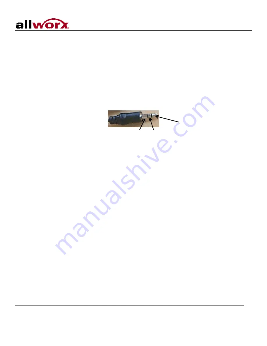
Note:   Only the white audio channel is used for music input. Red channel is for paging output (see Figure 4). 


Figure 4: Audio Plug Diagram 


Line Out

Line In 

GND


6.2 Overhead Paging 

Connect the server to the input of your paging system using a 3.5mm stereo plug audio cable. Insert the male 
cable end into the audio connector labeled Audio on the rear panel (See Figure 2 item 15). Only the red audio 
channel is used.  
 
Note:   Only the red audio channel is used for paging output. White channel is for hold input (see Figure 4). 

6.3 USB External Hard Drive 

To install a USB External Hard Drive: 
 
1.  Plug the USB data cable from the external hard drive into the USB port on the server and power on the 

USB drive. (See Figure 2 item 9).  

 
2.  Restart the server into Safe Mode.  
 
3.  In Safe Mode select Convert under Disk Operations.  
 
4.  Once the conversion is complete, power down the server. 
 
5.  Remove the Compact Flash. 
 
6.  Power on the system. Your hard drive should now be ready to use. 


Note:   Must use USB 2.0 based IDE hard drive directly plugged into unit (do not use with hub). 

6.4 Compact Flash Cards 

Unit comes pre-installed with a 512MB flash card. This card provides for approximately 800 minutes of 
voicemail storage. If more space is desired, use the USB External Hard Drive option (see section 6.3) or 


300 Main Street • East Rochester, NY 14445 • Toll Free 1-866-ALLWORX • 585-421-3850 • www.allworx.com 

© 2009 Allworx. All rights reserved 

Version 2. Revised: January 26, 2009 


Page 7 

Содержание 6x

Страница 1: ...Allworx 6x Server Installation Guide ...

Страница 2: ...ctronic mechanical photocopy recording or otherwise without the prior written permission of Allworx 2009 Allworx Corp a wholly owned subsidiary of PAETEC Holding Corp All rights reserved Allworx is a registered trademark of Allworx Corp All other names may be trademarks or registered trademarks of their respective owners ...

Страница 3: ...hassis Ground 6 5 2 Power Up Sequence 6 5 3 Safe Mode Sequence 6 6 Accessories Optional 7 6 1 Music On Hold 7 6 2 Overhead Paging 7 6 3 USB External Hard Drive 7 6 4 Compact Flash Cards 7 6 5 Door Relay Paging Amplifier Diagnostic Port 8 7 Configuring Handsets and Lines 10 7 1 Analog 10 7 2 SIP 10 8 Server Configuration 11 9 Data Network 12 10 Configuration Example 13 11 Physical and Environmental...

Страница 4: ...Version 2 Revised January 26 2009 Page 1 1 Installation Overview Installation of the Allworx 6x server involves the following steps 1 Unpacking 2 Mechanical Installation 3 Electrical Installation 4 Accessories Installation 5 Telephony Installation 6 Server Configuration 7 Network Installation Each of these steps will be described in the following sections ...

Страница 5: ...king Open the box and carefully unpack it Save all shipping and packaging materials Verify all items against the parts list shown in Table 1 If any items are missing contact your dealer or Allworx Customer Support at 866 255 9679 Quantity Item 1 Allworx 6x Server 1 Power Adapter 12 VDC 1A 1 6x Installation Instructions 1 Sheet of 4 Rubber Feet 1 Compact Flash Card installed in server Table 1 Parts...

Страница 6: ...lease Normal shutdown within a few seconds Press Hold Forced shutdown 2 Power LED Indicates system start up activity 3 Outside Analog Phone Line LEDs Indicates status of a particular FXO port 4 Inside Analog Extension LEDs Indicates status of a particular FXS port 5 Network LEDs Indicates Ethernet link status flashes off for activity 6 Drive Activity LEDs Green indicates mounted drive flashes off ...

Страница 7: ...port 12 RJ 11 FXS ports for inside extensions Ports 7 8 13 RJ 11 loop start FXO for central office connection Ports 1 6 14 RJ 11 Power Fail analog phone connector 15 3 5 mm stereo audio mini jack for music on hold input and overhead paging output 16 Ground connecting screw 17 5 5 x 2 1 mm power jack Input 12 VDC 1A center positive 300 Main Street East Rochester NY 14445 Toll Free 1 866 ALLWORX 585...

Страница 8: ...ficient clearance around the server s front and rear panels to allow power network and telephony connections 2 Use self drilling drywall anchors rated for at least 20 lbs with screws that are either 6 or 8 Locate two anchors that will support the upper end of the unit using the wall mount template included in Section 13 Install the anchors per the anchor manufacturer s recommendation Install the m...

Страница 9: ...ure 3 Wall Mount Orientation Correct Orientation Wrong Orientation 300 Main Street East Rochester NY 14445 Toll Free 1 866 ALLWORX 585 421 3850 www allworx com 2009 Allworx All rights reserved Version 2 Revised January 26 2009 Page 5 ...

Страница 10: ...ce the front panel lights will respond as shown in Table 2 Front Panel Light Power Up Sequence Description Power Flashes green as the power up sequence progresses lights steady green when the unit is ready Drive Activity CF Flashes green when drive mounted flashes off for activity Table 2 Front Panel Lights During Power Up Sequence 5 3 Safe Mode Sequence When the unit is off if the power button is...

Страница 11: ...red audio channel is used for paging output White channel is for hold input see Figure 4 6 3 USB External Hard Drive To install a USB External Hard Drive 1 Plug the USB data cable from the external hard drive into the USB port on the server and power on the USB drive See Figure 2 item 9 2 Restart the server into Safe Mode 3 In Safe Mode select Convert under Disk Operations 4 Once the conversion is...

Страница 12: ...et up the PC s network interface to obtain an IP address automatically using DHCP 4 You may need to release and renew the PC s IP address to get an address from the server 5 Verify that the PC has an IP address on the 192 168 2 xxx network 6 Open your browser and enter the URL of http 192 168 2 254 8080 or current IP address 7 In Safe Mode select Format under Disk Operations 8 Click OK to format 9...

Страница 13: ...e diagnostic data connect a null modem serial cable from the Door and Paging Relay connector to the serial port on a PC Configure the PC port in accordance with the following table Baud 9600 Data Bits 8 Parity None Stop Bits 1 Flow Control None Table 5 Serial Port Configuration To configure the door relay paging amplifier 1 Open your browser and enter the URL of http 192 168 2 254 8080 or current ...

Страница 14: ...ce that is operational in the event that the server loses power or fails During power failure it automatically connects to the first outside phone line port port 1 Surge protection is provided internally on all telephony interfaces Under normal operation of the unit the port LEDs will appear as shown in Table 7 Port 1 8 State LED Indicator Normal Idle Off Off Hook Green Solid Ringing Green Fast Bl...

Страница 15: ...r the URL of http 192 168 2 254 8080 or current IP address 6 When the Welcome to Allworx page appears login using the default password of admin When the Home page appears click on the Install Checklist link on the left hand side to bring up a new window containing steps necessary to set up a new system Each brief step description is followed by a link to get to the appropriate administrative web p...

Страница 16: ...nd WAN Note Do not plug any network or ISP service into the server without first properly configuring the server Failure to heed this warning may result in a disruption of network connectivity with other equipment on the network After the unit is properly configured the LAN and WAN network infrastructure cables can be plugged in Standard RJ 45 category 5 network cables must be used The LED s on th...

Страница 17: ...ide 10 Configuration Example Figure 5 Configuration Example 300 Main Street East Rochester NY 14445 Toll Free 1 866 ALLWORX 585 421 3850 www allworx com 2009 Allworx All rights reserved Version 2 Revised January 26 2009 Page 13 ...

Страница 18: ...9 Allworx All rights reserved Version 2 Revised January 26 2009 Page 14 11 Physical and Environmental Specifications Dimensions W x H x D 12 1 x 1 9 x 7 6 inches 30 8 x 4 8 x 19 3 cm Weight Base Model 3 lbs Power DC 12V 1 Amp Temperature 0 40 C Humidity 15 90 RH Non condensing Table 9 Physical and Environmental Specifications ...

Страница 19: ...ermine the number of devices that may be connected to a telephone line Excessive RENs on a telephone line may result in the devices not ringing in response to an incoming call In most but not all areas the sum of RENs should not exceed five 5 0 To be certain of the number of devices that may be connected to a line as determined by the total RENs contact the local telephone company For products app...

Страница 20: ...egistration was performed based on a Declaration of Conformity indicating that Industry Canada technical specifications were met It does not imply that Industry Canada approved the equipment AVIS Le présent matériel est conforme aux spécifications techniques d Industrie Canada applicables au matériel terminal Cette conformité est confirmée par le numéro d enregistrement Le sigle IC placé devant le...

Страница 21: ...ced radio TV technician for help You may also find helpful the following booklet prepared by the FCC How to Identify and Resolve Radio TV Interference Problems This booklet is available from the U S Government Printing Office Washington D C 20402 Changes and Modifications not expressly approved by the manufacturer or registrant of this equipment can void your authority to operate this equipment un...

Страница 22: ... Installation Guide 13 Wall Mount Template 300 Main Street East Rochester NY 14445 Toll Free 1 866 ALLWORX 585 421 3850 www allworx com 2009 Allworx All rights reserved Version 2 Revised January 26 2009 Page 18 ...

Отзывы: