Alloy POE2000 Series Скачать руководство пользователя страница 7


5. WDM Single Fibre Model 


The POE2000 Series media converter has an optional Wavelength Division 
Multiplexing (WDM) Model that can transport bi-directional full duplex signals 
over a single fibre simultaneously. 
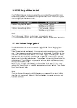
 

Single Fibre Model 

TX, RX Wavelength 

1310nm Single Mode 20Km 
 

TX (Transmit) 1310nm 
RX (Receive) 1550nm 

1550nm Single Mode 20Km 

TX (Transmit) 1550nm 
RX (Receive) 1310nm 


Note: 

The 1310nm and 1550nm models must be installed in pairs, 
i.e., install 1310nm model at one end and the 1550nm model at the other end. 


6. Link Failure Propagation 


The POE2000 Series media converters support Link Failure Propagation 
(LFP). 
If the Copper port is unplugged, the converter stops transmission on the fibre 
port.  This causes the remote fibre node link to fail as well.  The LED

’s on the 

converter will now show link failure on both the copper and fibre ports.  If the 
fibre link fails, the converter restarts auto-negotiation on the copper port but 
always stays in the link failure state.  This causes the remote copper node link 
to fail as well.  The LED

’s on the converter will now show link failure on both 

the copper and fibre ports.   
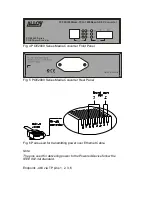
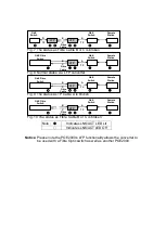
Refer to Fig. 7 shown below for the normal status when link is active.  Also 
refer to Fig. 8 and Fig. 9 for the LED status when copper Cable A, Fibre Cable 
B or Fibre Cable C fails. 
 

Note:   

The Link Failure Propagation (LFP) function only takes effect when S1-Bit4 
(see Fig. 10) is enabled.  When S1-Bit2 is disabled the media converter will 
function normally. 


Содержание POE2000 Series

Страница 1: ...POE2000 Series 10 100 1000Base TX to 1000Base SX LX and SFP Converter POE Power Provider Version 1 01 Date October 2009 ...

Страница 2: ...its for a Class A computing device pursuant to Subpart J of Part 15 of FCC Rules which are designed to provide reasonable protection against such interference when operated in a commercial environment European Community CE Electromagnetic Compatibility Directive This equipment has been tested and found to comply with the protection requirements of European Emission Standard EN55022 EN60555 2 and t...

Страница 3: ...af standard The converters include PD Power Devices POE120 Series IP Phones Wireless Access Points etc signature sensing and power monitoring features compliant with the IEEE 802 3af standard including PD discovery classification current limiting and other necessary functions It also supports high levels of safety support with short circuit protection and power out auto detection to the PD 2 Model...

Страница 4: ...er source 2 Connect the copper cable to your IEEE 802 3af compliant PD device e g Wireless Access Point IP Phone IP Camera Note The POE2000 can also work as a standard media converter and connect to a non POE device 3 Connect the fibre cable to your connecting device TP Port 10 100Base TX Auto Negotiation Auto MDIX flow control for Full Duplex backpressure for Half Duplex 1000Base TX Auto Negotiat...

Страница 5: ... Converter Fig 2 Example connection between POE2000 PD device and Fibre Cable Fig 3 POE200 Series to PD Device or POE Splitter VOIP Phone RX TX TX RX VOIP PoE Phone PoE PD or PoE Splitter POE100 Series Media Converter AC 100FX Fibre Network ...

Страница 6: ...ig 4 POE2000 Series Media Converter Front Panel Fig 5 POE2000 Series Media Converter Rear Panel Fig 6 Pairs used for transmitting power over Ethernet Cable Note The pins used for delivering power to the Powered Device follow the IEEE 802 3af standard Endpoint 48V via TP pins 1 2 3 6 ...

Страница 7: ...is unplugged the converter stops transmission on the fibre port This causes the remote fibre node link to fail as well The LED s on the converter will now show link failure on both the copper and fibre ports If the fibre link fails the converter restarts auto negotiation on the copper port but always stays in the link failure state This causes the remote copper node link to fail as well The LED s ...

Страница 8: ...ble B or C is broken Fig 9 The status as TP Cable A is broken Fig 8 Normal status via LFP converter Fig 7 The status as Fibre Cable B or C is broken LFP LFP GbE Switch GbE Switch Remote Station A Fibre Cable TP B C D TP LFP GbE Fibre Switch GbE Switch Remote Station A Fibre Cable TP B C LFP GbE Fibre Switch GbE Switch Remote Station A Fibre Cable TP B C LFP GbE Fibre Switch GbE Switch Remote Stati...

Страница 9: ...it when PoE feeding power is disrupted In case of overtemperature overcurrent 4W Green Light when PD Class Type is Class 1 7W Green Light when PD Class Type is Class 2 15 4W Green Light when PD Class Type is Class 0 or 3 8 DIP Switch and Reset Button Reset Once S1 1 S1 2 is changed please press this button to have the settings take effect S1 1 Bridge mode Cut through default or Normal S1 2 LFP LFP...

Страница 10: ...00Base T IEEE802 3af Power over Ethernet UTP Cable Cat 5 cable and up to100m Fibre Cable 50 125 62 5 125 or 100 140 m multi mode 8 3 125 8 7 125 9 125 or 10 125 m single mode PSE Power Feeding Supports Endpoint via TP pin 1 2 3 6 LED Indicators POWER PoE TP LNK ACT SPD FX LNK ACT 4W 7W 15 4W Data Transfer Rate Speed Forwarding Rate 1000Mbps 148 8000 PPS 100Mbps 148 800 PPS 10Mbps 14 880 PPS Flow C...

Отзывы: