ALLNIC AUDIO L-8000 DHT Скачать руководство пользователя страница 9


CLEANING


A.


Chassis and glass 


Use only a soft, lint-free cloth dampened slightly with water only (NO cleaning fluids!) to clean 

the faceplate, meter glass and chassis. 


B.


Connectors 


You may use any good quality contact cleaner recommended for such applications to clean the 

contacts from time to time as you deem appropriate. 


INITIAL SET-UP


A. 

LOCATION, LOCATION, LOCATION 


Like all audio products using tubes, the Allnic Audio L-8000 DHT needs to be placed on a solid 

stand in a location that provides for good air circulation around the preamplifier. 


DO NOT cover the top of the preamplifier. 


DO NOT place the unit on carpet or foam. 


DO NOT subject the unit to knocks and shocks as you move it around. This advice is 

meant particularly for those who may want to place the L-8000 DHT on a set of after-

market isolation feet or similar devices. Dropping one side of the L-8000 DHT, or the 

whole unit, is not a good thing. 


DO NOT place the unit near a strong light or heat source. 


DO NOT place anything heavy on the unit.


DO NOT allow rubber or vinyl materials to rest on the unit’s chassis for long periods of 

time. This could discolour the metal.


DO place the unit on a shelf or stand that is stable and not subject to vibration or 

sudden shock. 


DO consider using a high quality power cord and inter-connects, both inputs and 

outputs. The L-8000 DHT is a highly sensitive piece of electronic equipment designed for 

neutrality and will output what you put into it. Allnic’s Zero Loss Technology cables will 

work synergistically with the L-8000 DHT. 


DO try to place the L-8000 DHT away from major sources of RFI and EMI; though well 

shielded, the L-8000 DHT will function best away from large power transformers and 

other sources of such interference. 


B. 

POWER CONNECTION 


The L-8000 DHT uses a standard three prong male 15 amp IEC connection for AC input. You need 

to use a power cord with a female three prong 15 amp IEC connector at one end. 


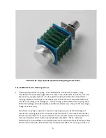
To the left of the IEC connector (facing the left side of the unit as in Figure 1), there is a power 

on-off switch. Leave this switch in the OFF position – that means the switch is pressed “down” at 

the bottom - while you make all initial connections. 


Содержание L-8000 DHT

Страница 1: ...ALLNIC AUDIO L 8000 DHT LINE STAGE PREAMPLIFIER OWNER S MANUAL...

Страница 2: ...ty device will be rewarded by its excellent operation for years to come Please read this entire manual before you connect the L 8000 DHT Line Stage Preamplifier to the other components of your system...

Страница 3: ...AL SET UP Location Location Location Power Connection Inputs Outputs Remote Control 9 INITIAL POWER ON 11 OPERATION 12 TUBES 12 SPECIFICATIONS 13 WARRANTY 14 FIGURES 14 Please read about SAFETY before...

Страница 4: ...s of circuit designs for them and experimenting constantly in a framework of rigorous application of theory Mr Park s work has resulted in some remarkable audio power amplification devices With the 30...

Страница 5: ...le to secure a limited number of these valves enough to produce an also limited number of the L 8000 DHT preamplifier ONLY A LIMITED NUMBER OF UNITS OF THIS DESIGN WILL BE MADE This allows for valve s...

Страница 6: ...e not real energy With transformer coupling about 90 of real wattage is transferred there is still a transformer loss of about 10 of wattage voltage is not affected Transformer coupling is superior to...

Страница 7: ...be damping technology Allnic Audio s patented Absorb GEL tube damper technology prevents harmful vibrations from reaching the signal gain tubes and therefore prevents microphonic noise propagation in...

Страница 8: ...e of your location If it is not DO NOT connect it to your AC outlet Please contact your Allnic dealer We advise that you keep the box and other packing materials that your L 8000 DHT came in It will b...

Страница 9: ...ything heavy on the unit DO NOT allow rubber or vinyl materials to rest on the unit s chassis for long periods of time This could discolour the metal DO place the unit on a shelf or stand that is stab...

Страница 10: ...lect either the balanced or single ended connections This selection switch is at the top centre of the rear panel and labeled unbalanced output see Figure 2 Please set the output selection switch to t...

Страница 11: ...he volume control on the front panel to the extreme counter clockwise position minimum volume Push the power on off switch to the left of the IEC connector facing the left side of the unit as in Figur...

Страница 12: ...e L 8000 DHT They are indicators of failure or damage to the function of the unit There is one meter for each channel The needle should be between the two parallel lines just left of centre on the met...

Страница 13: ...1kHz Output 0 3V 0 06 Output 1 0V 0 16 S N Ratio 90dB CCIR 1kHz Maximum Output 20V RMS Non clipping Output Impedance 120 Constant Power Consumption 30W at 110 120V 60 Hz Tubes 3A 110A or lower gain st...

Страница 14: ...s warranty period provided as stated below no unauthorized repairs or modifications have been performed on the product Date of purchase is the date indicated on the invoice for the product issued by...

Страница 15: ...15 Figure 2 L 8000 DHT Rear Panel View Figure 3 L 8000 DHT Remote Control Figure 4 L 8000 DHT Front Panel View...

Страница 16: ...16 Figure 5 L 8000 DHT Top View...

Отзывы: