


376
STEP 4
﹒
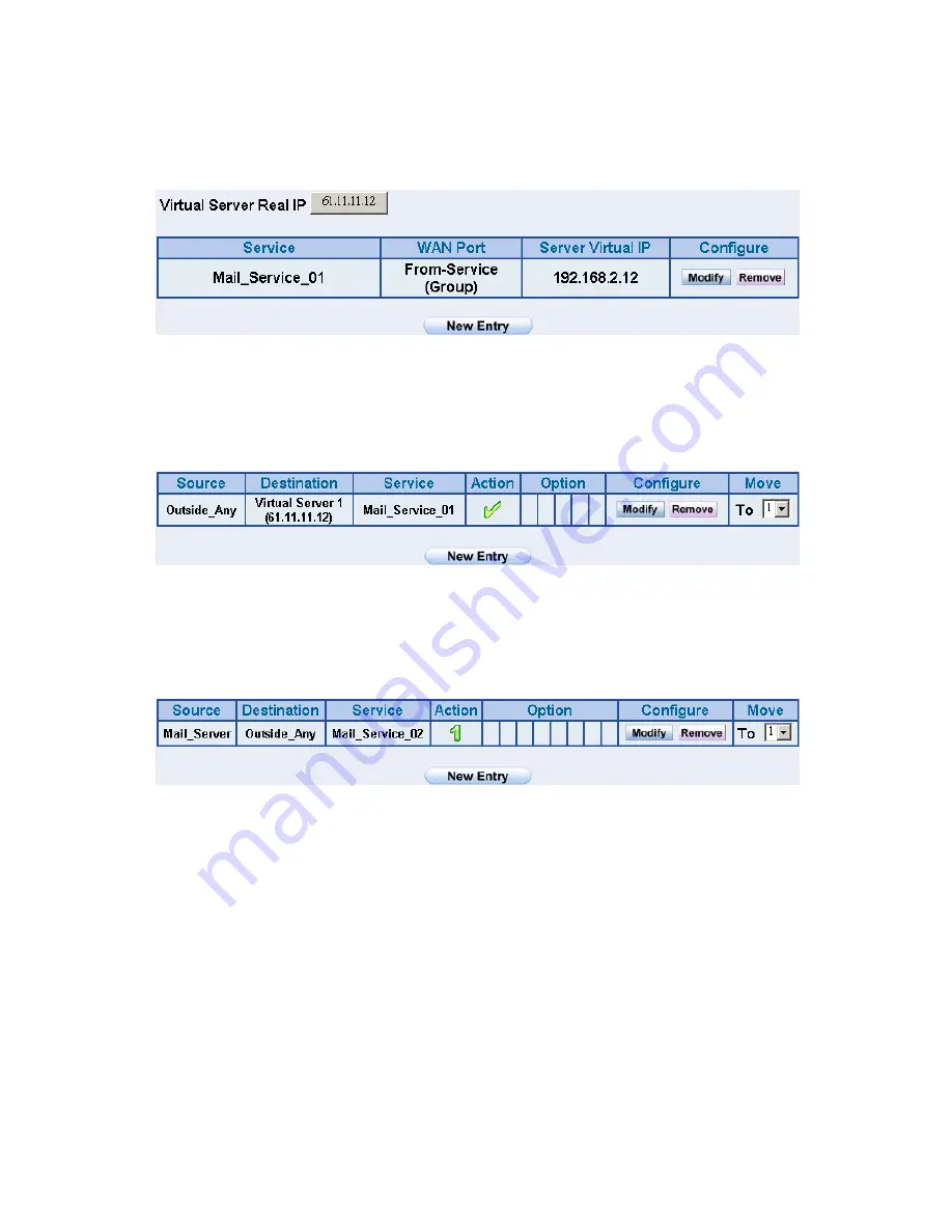
Enter the following setting in
Server1
in
Virtual Server
function:
(Figure15-11)
Figure15-11 Virtual Server Setting WebUI
STEP 5
﹒
Enter the following setting in
Incoming Policy
: (Figure15-12)
Figure15-12 Incoming Policy Setting
STEP 6
﹒
Enter the following setting in
Outgoing Policy
: (Figure15-13)
Figure15-13 Outgoing Policy Setting
Содержание ALL7008
Страница 1: ...ALL7008 User s Manual...
Страница 5: ...4 Chapter21 Status 423 Interface 424 Authentication 426 ARP Table 427 DHCP Clients 428...
Страница 13: ...12...
Страница 36: ...35 STEP 4 Complete PPTP VPN Connection Figure 2 20 Figure 2 20 PPTP VPN Connection Setting...
Страница 43: ...42...
Страница 55: ...54 Figure3 8 Complete Dynamic IP Connection Setting...
Страница 83: ...82...
Страница 85: ...84 Figure7 2 the Flow After Using QoS Max Bandwidth 400Kbps Guaranteed Bandwidth 200Kbps...
Страница 109: ...108 STEP 5 Press right button on RADIUS Clients and choose New RADIUS Client Figure8 18 Figure8 18 Add New RADIUS Client...
Страница 114: ...113 STEP 10 Select Ethernet Figure8 23 Figure8 23 Add New Remote Access Policy Method...
Страница 115: ...114 STEP 11 Choose User Figure8 24 Figure8 24 Add New Remote Access Policy of User or Group Access...
Страница 116: ...115 STEP 12 Select MD5 Challenge Figure8 25 Figure8 25 Authentication Methods of Adding New Remote Access Policy...
Страница 119: ...118 STEP 15 Add Service Type Figure8 28 Figure8 28 Add New RADIUS Attribute...
Страница 120: ...119 STEP 16 Add Authenticate Only from the left side Figure8 29 Figure8 29 Add RADIUS Service Type...
Страница 145: ...144...
Страница 165: ...164...
Страница 188: ...187 STEP 5 Select Local computer to complete adding Figure11 36 Figure11 36 Select Computer or Domain...
Страница 191: ...190 STEP 8 Click on Next Figure11 39 Figure11 39 Enable IP Security Policy...
Страница 196: ...195 STEP 13 Click on Add in New Rule Properties WebUI Figure11 44 Figure11 44 Add New IP Filter List...
Страница 199: ...198 STEP 16 Complete the setting and close IP Filter List Window Figure11 47 Figure11 47 Complete IP Filter List...
Страница 200: ...199 STEP 17 Select Require Security in Filter Action WebUI and click Edit Figure11 48 Figure11 48 Filter Action Setting...
Страница 202: ...201 STEP 19 Please select Custom None 3DES MD5 and click Edit Figure11 50 Figure11 50 Edit Security Method...
Страница 205: ...204 STEP 22 Enter Connection Type and select All network connections Figure11 53 Figure11 53 Connection Type Setting...
Страница 209: ...208 STEP 26 Complete Setting and close the WebUI Figure11 57 Figure11 57 Complete Authentication Methods Setting...
Страница 210: ...209 STEP 27 Complete the VPN_B WAN TO LAN Settings Figure11 58 Figure11 58 Complete VPN_B WAN TO LAN Setting...
Страница 212: ...211 STEP 29 Please select Add in New Rule Properties WebUI Figure11 60 Figure11 60 Add New Rule Properties WebUI...
Страница 215: ...214 STEP 32 Complete Setting and close IP Filter List WebUI Figure11 63 Figure11 63 Complete IP Filter List Setting...
Страница 216: ...215 STEP 33 Select Require Security in Filter Action WebUI and click Edit Figure11 64 Figure11 64 Filter Action WebUI...
Страница 218: ...217 STEP 35 Select Custom None 3DES MD5 and choose Edit Figure11 66 Figure11 66 Setting Security Methods...
Страница 221: ...220 STEP 38 Select All network connections in Connection Type Figure11 69 Figure11 69 Connection Type Setting...
Страница 225: ...224 STEP 42 Complete Setting and close the WebUI Figure11 73 Figure11 73 Complete New Rule Properties Setting...
Страница 226: ...225 STEP 43 Complete VPN_B LAN TO WAN Settings Figure11 74 Figure11 74 Complete VPN_B LAN TO WAN Setting...
Страница 234: ...233 STEP 51 Please select Services item after entering Administrative Tools Figure11 82 Figure11 82 Enter Services item...
Страница 236: ...235 STEP 53 Complete all of the settings Figure11 84 Figure11 84 The IPSec VPN Setting of ALL7008 and Windows 2000...
Страница 245: ...244 STEP 10 Complete IPSec VPN Aggressive Mode Settings Figure11 103 Figure11 103 IPSec VPN Aggressive Mode Settings...
Страница 255: ...254 STEP 11 Complete IPSec VPN GRE IPSec Setting Figure11 124 Figure11 124 IPSec VPN GRE IPSec Setting...
Страница 260: ...259 STEP 4 Complete PPTP VPN Connection Figure11 128 Figure11 128 PPTP VPN Connection Setting...
Страница 267: ...266 STEP 4 Click OK in Phone And Modem Options WebUI Figure11 134 Figure11 134 Phone and Modem Options WebUI...
Страница 268: ...267 STEP 5 Click on Next in Network Connection Wizard Figure11 135 Figure11 135 Network Connection Wizard WebUI...
Страница 274: ...273 Figure11 142 PPTP VPN Connection Complete...
Страница 275: ...274 STEP 11 Complete PPTP VPN Connection Settings Figure11 143 Figure11 143 PPTP VPN Connection Setting...
Страница 301: ...300...
Страница 343: ...342 Figure14 34 Create Folder WebUI...
Страница 345: ...344 Figure14 36 Select Folder for Spam Mail to move to...
Страница 347: ...346 Figure14 38 Compact SpamMail Folder...
Страница 349: ...348 Figure14 40 Copy the File Address that SpamMail File Store...
Страница 353: ...352 Figure14 43 Confirm that All of the Mail in SpamMail File had been Deleted...
Страница 355: ...354 Figure14 45 Create Folder Function WebUI...
Страница 357: ...356 Figure14 47 Select the Folder for Needed Spam Mail to Move to...
Страница 359: ...358 Figure14 49 Compact HamMail File...
Страница 361: ...360 Figure14 51 Copy the File Address that HamMail File Store...
Страница 364: ...363 Figure14 54 Make Sure all of the Mails in HamMail File had been Deleted...
Страница 365: ...364...
Страница 381: ...380...
Страница 389: ...388 Figure16 4 NetBIOS Alert Notification to Administrator s PC...
Страница 390: ...389 Figure16 5 E mail Virus Alert...
Страница 391: ...390...
Страница 397: ...396...
Страница 413: ...412...
Страница 417: ...416...
Страница 426: ...425 Figure21 1 Interface Status...
Страница 430: ...429...


