


508298-01
Page 10 of 55
Issue 2219
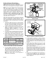
Figure 11. Setting Equipment
FRONT VIEW
SIDE VIEW
AIR FLOW
AIR FLOW
1/2"
max.
AIR FLOW
SIDE VIEW
Unit must be level side−to−side. Unit may be positioned
from level to 1/2" toward the front to aid in draining.
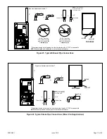
Figure 12.
Improper installation of the furnace can result in
personal injury or death. Combustion and flue products
must never be allowed to enter the return air system or
air in the living space. Use sheet metal screws and joint
tape to seal return air system to furnace.
In platform installations with furnace return, the furnace
should be sealed airtight to the return air plenum. A door
must never be used as a portion of the return air duct
system. The base must provide a stable support and an
airtight seal to the furnace. Allow absolutely no sagging,
cracks, gaps, etc.
For no reason should return and supply air duct systems
ever be connected to or from other heating devices
such as a fireplace or stove, etc. Fire, explosion, carbon
monoxide poisoning, personal injury and/or property
damage could result.
WARNING
The unit may be installed three ways in downflow
applications: on non-combustible flooring, on combustible
flooring using an additive base, or on a reverse-flow
cooling coil cabinet. Do not drag the unit across the floor
in the downflow position. Floor and furnace flange damage
will result.
Refer to Figure 13 for clearances in downflow applications.
Top
Bottom
Left Side
Right Side
Top
0
*Front
0
Back
0
Sides
0†
Vent
0
Floor
NC
‡
*Front clearance in alcove installation must be 24 in. (610 mm).
Maintain a minimum of 24 in. (610 mm) for front service access.
†Allow proper clearances to accommodate condensate trap.
‡
The furnace may be installed on a combustible wood floor if an optional
additive base is installed between the furnace and the combustible floor.
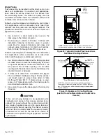
Figure 13.
Downflow Application Installation
Clearances
Top
0
*Front
0
Back
0
Sides
0†
Vent
0
Floor
NC‡
*Front clearance in alcove installation must be 24 in. (610
mm). Maintain a minimum of 24 in. (610 mm) for front service
access.
†Allow proper clearances to accommodate condensate trap.
‡The furnace may be installed on a combustible wood floor if
an optional additive base is installed between the furnace and
the combustible floor.
Installation on Non-Combustible Flooring
1. Cut floor opening keeping in mind clearances listed
on unit rating plate. Also keep in mind gas supply
connections, electrical supply, flue and air intake
connections and sufficient installation and servicing
clearances. See Table 1 for correct floor opening size.
2. Flange warm air plenum and lower the plenum into the
opening.
3. Set the unit over the plenum and seal the plenum to
the unit.
4. Ensure that the seal is adequate.
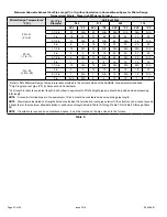
Table 1.
Non-Combustible Floor Opening Size
Cabinet Width
Front to Rear
Side to Side
in.
mm
in.
mm
B cabinet (17.5”)
19-3/4
502
16-5/8
422
C cabinet (21”)
19-3/4
502
20-1/8
511
NOTE
: Floor opening dimensions listed are 1/4 inch (6 mm)
Содержание A96DF1E
Страница 32: ...508298 01 Page 32 of 55 Issue 2219 Figure 50 Trap Drain Assembly Using 1 2 PVC or 3 4 PVC ...
Страница 38: ...508298 01 Page 38 of 55 Issue 2219 045 B12 070 B16 090 C16 110 C20 Figure 57 Typical Wiring Diagram ...
Страница 51: ...508298 01 Page 51 of 55 Issue 2219 Troubleshooting Heating Sequence of Operation ...
Страница 52: ...508298 01 Page 52 of 55 Issue 2219 Troubleshooting Heating Sequence of Operation continued ...
Страница 53: ...508298 01 Page 53 of 55 Issue 2219 Troubleshooting Cooling Sequence of Operation ...
Страница 54: ...508298 01 Page 54 of 55 Issue 2219 Troubleshooting Continuous Fan Sequence of Operation ...