507335-02
Page 10 of 39
Issue 2001
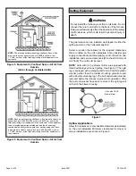
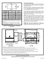
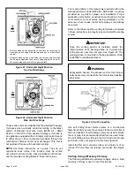
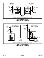
Figure 11. Horizontal Application Installation
Clearances
Type of Vent
Connector
Type C
Type B1
Top
0
0
* Front
2-1/4 in. (57 mm)
2-1/4 in. (57 mm)
Back
0
0
Sides
2 in. (51 mm)
2 in. (51 mm)
Vent
6 in. (152 mm)
1 in. (25 mm)
Floor
0‡
0‡
* Front clearance in alcove installation must be 24 in. (610
mm). Maintain a minimum of 21 in. (610 mm) for front service
access.
‡ For installations on a combustible floor, do not install
the furnace directly on carpeting, tile or other combustible
materials other than wood flooring.
Horizontal Applications
The furnace can be installed in horizontal applications.
Order horizontal suspension kit (51W10) or use equivalent
suspension method.
Allow for clearances to combustible materials as indicated
on the unit nameplate. Minimum clearances for closet or
alcove installations are shown in Figure 11.
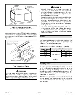
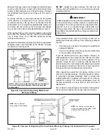
This furnace may be installed in either an attic or a crawl
space. Either suspend the furnace from roof rafters or floor
joists, as shown in Figure 13, or install the furnace on a
platform, as shown in Figure 14.
NOTE:
Heavy gauge perforated sheet metal straps may
be used to suspend the unit from roof rafters or ceiling
joists. When straps are used to suspend the unit in this
way, support must be provided for both the ends. The
straps must not interfere with the plenum or exhaust
piping installation. Cooling coils and supply and return air
plenums must be supported separately.
NOTE:
When the furnace is installed on a platform in a
crawlspace, it must be elevated enough to avoid water
damage and to allow the evaporator coil to drain.
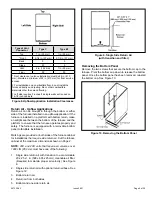
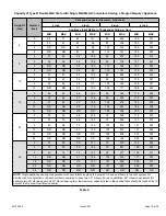
Figure 12. Optional Return Air Base
(Upflow Applications Only - For use with A, B, C and D cabinets)
FRONT VIEW
1
Unit side return air
Opening
SIDE VIEW
3−1/4
(83)
1
23 (584)
Overall
(Maximum)
(584)
23
3/4
(19)
1
22−7/16
(570)
Overall
(Maximum)
SIDE RETURN
AIR OPENINGS
(Either Side)
5−5/8
(143)
1
Minimum
11 (279)
2
Maximum
14 (356)
(683)
26−7/8
7−1/4
(184)
FURNACE
FRONT
AIR FLOW
IF BASE
IS USED
WITHOUT
IAQ CABINET,
A SINGLE
RETURN AIR
PLENUM
MUST
COVER BOTH
UNIT AND
RETURN
AIR BASE
OPENINGS
INDOOR AIR
QUALITY
CABINET
AIR BASE
OPTIONAL
RETURN
17-1/2 (446) B Width (68W62)
21 (533) C Width (68W63)
24-1/2 (622) D Width (68W64)
14-1/2 (368) A Width (68W61)
NOTE:
Optional Side Return Air Filter Kits are not for use with Return Air Base.
1 Both the unit return air opening and the base return air opening must be covered by a single plenum or IAQ cabinet.
Minimum unit side return air opening dimensions for units requiring 1800 cfm or more of air (W x H): 23 x 11 in. (584 x 279 mm).
The opening can be cut as needed to accommodate plenum or IAQ cabinet while maintaining dimensions shown.
Side return air openings must be cut in the field. There are cutting guides stenciled on the cabinet for the side return air opening.
The size of the opening must not extend beyond the markings on the furnace cabinet.
² To minimize pressure drop, the largest opening height possible (up to 14 inches) is preferred.


