AT-TS90-TR 10Base-T Switch With 100Base-T Access
11
Complete Installation Instructions
The following section contains detailed installation instructions for your
AT-TS90TR.
TurboStack Chassis
Installation
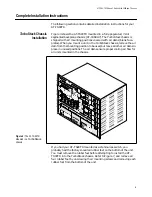
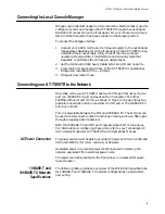
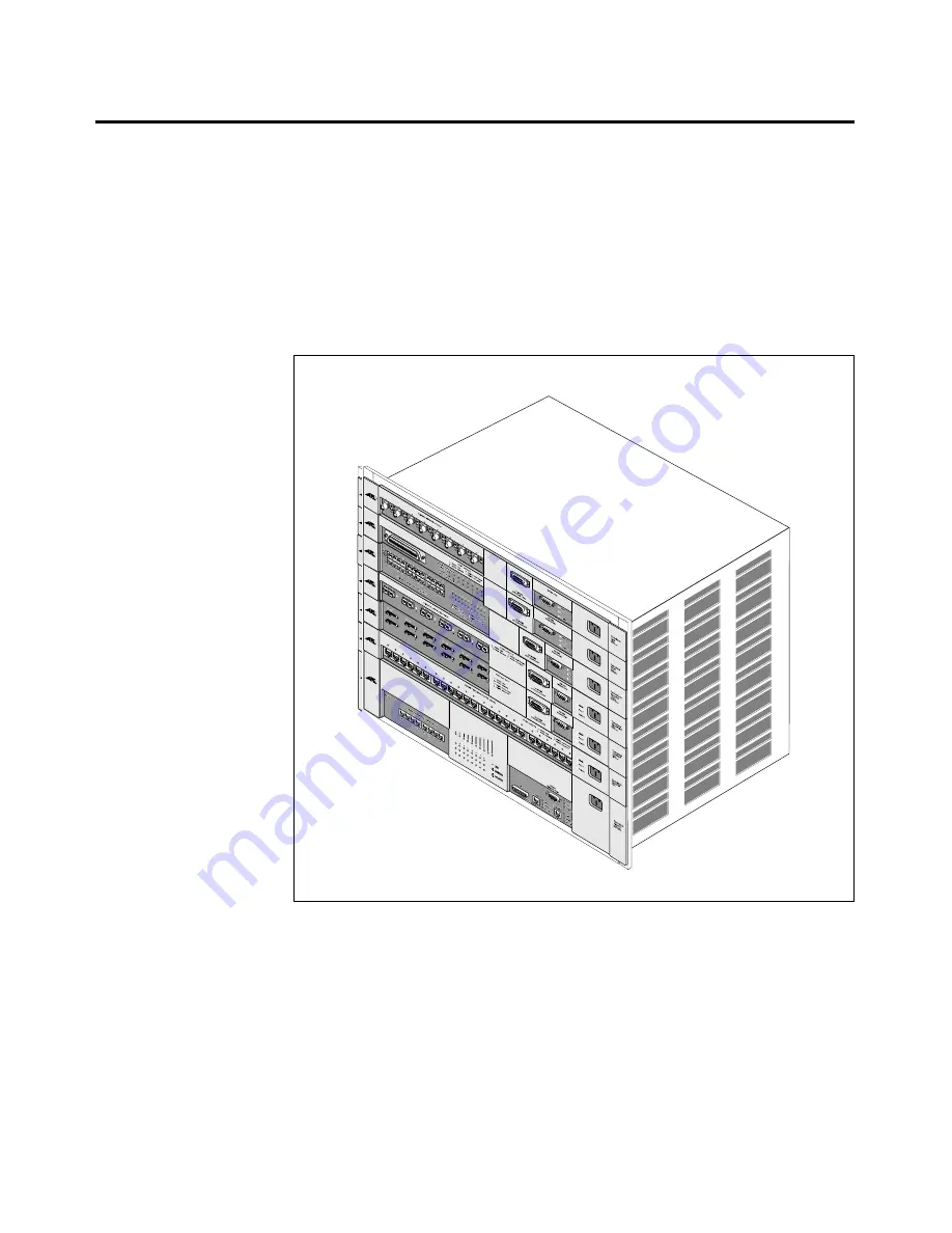
Figure 4 shows the AT-TS90TR mounted in a fully-populated, 7-slot
segmented backplane chassis (AT-C36RG7). The TurboStack chassis is
shipped with all mounting positions covered with air dams (blank face-
plates). When you mount a unit in the TurboStack chassis, remove the air
dam from the mounting position to be used, but leave all other air dams in
place in unused positions. The air dams ensure proper cooling air flow for
all units mounted in the chassis.
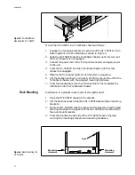
If you had your AT-TS90TR mounted as a stand-alone switch, you
probably had the factory-mounted rubber feet on the bottom of the unit.
You must remove the rubber feet before attempting to install the AT-
TS90TR into the TurboStack chassis. Refer to Figure 7, and remove all
four rubber feet by unscrewing their mounting screws and removing each
rubber foot from the bottom of the unit.
Figure 4: The AT-TS90TR
Mounted in a
TurboStack
chassis


