613-003079 Rev. A
*613-003079 Rev A*
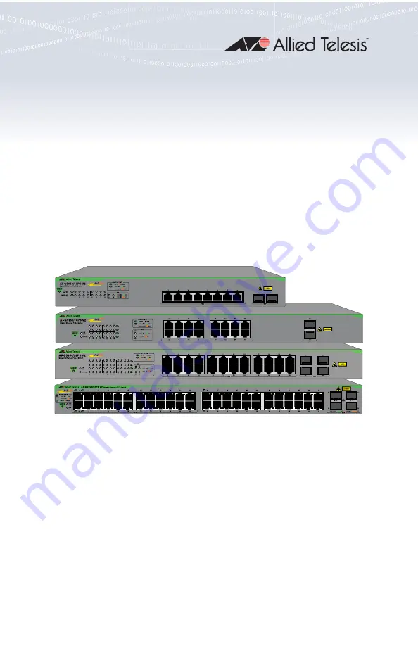
GS950PS V2 Series
Gigabit WebSmart Ethernet Switches
GS950/10PS V2GS950/18PS V2GS950/28PS V2GS950/52PS V2
Quick Installation Guide
Страница 1: ...613 003079 Rev A 613 003079 Rev A GS950PS V2 Series Gigabit WebSmart Ethernet Switches GS950 10PS V2 GS950 18PS V2 GS950 28PS V2 GS950 52PS V2 Quick Installation Guide...
Страница 2: ...lesis web site at www alliedtelesis com us en services support This guide contains the following sections Front Panels next PoE Power Budgets on page 4 Beginning the Installation on page 4 Installing...
Страница 3: ...port LEDs 4 SFP ports LEDs 5 10 100 1000Mbps Ethernet copper ports with PoE 6 100Mbps and 1Gbps SFP transceiver ports 7 Ports 25 to 48 10 100 1000Mbps Ethernet copper on the GS950 52PS V2 Switch no P...
Страница 4: ...g Safety Precautions Review the following safety precautions before installing the product Note The symbol indicates that a translation of the safety statement is available in the PDF document Transla...
Страница 5: ...k disconnect electric power to the product before connecting or disconnecting the cables E1 Warning Class I Equipment This equipment must be earthed The power plug must be connected to a properly wire...
Страница 6: ...Switch on a wall requires the BRKT J22 kit The kit is sold separately Unpacking the Switch The switches come with these items Eight 3 5mm x 16mm wall screws and washers Eight 4mm x 22 2mm wall anchor...
Страница 7: ...rify that the table is level and stable Before installing the switch on a wall verify that the wall s material is strong enough to hold the switch s weight You should position the device so that it ca...
Страница 8: ...down Direction of Ventilation in the Switches The GS950 18PS V2 GS950 28PS V2 and GS950 52PS V2 Switches have internal ventilation fans Airflow is from left to right when facing the front of the switc...
Страница 9: ...panel of the switch remove them with a flat head screwdriver 3 Attach the two brackets to the sides of the switch with the eight M3 3mm x 6mm screws included with the switch This figure shows the GS9...
Страница 10: ...sold separately For installation instructions refer to the GS950PS V2 Gigabit Ethernet Switch Series Installation Guide on the Allied Telesis web site at www alliedtelesis com us en services support Y...
Страница 11: ...or a concrete wall not provided To install the switch on a wall perform the following procedure 1 Place the switch on a table 2 If the four bumper feet are attached to the bottom of the switch remove...
Страница 12: ...the switch on a table 6 Use a stud finder to check for hot electrical wires at the locations of the screw holes 7 Use an appropriate drill to drill the holes The dimensions of the supplied anchors ar...
Страница 13: ...Ethernet Copper Ports Observe the following guidelines when connecting Ethernet copper cables to the ports on the switch The connectors on the cables should fit snugly into the ports and the tabs shou...
Страница 14: ...ations and fiber optic cable requirements are included with the transceivers Install the transceivers before connecting their fiber optic cables Fiber optic transceivers are dust sensitive Always keep...
Страница 15: ...o the transceiver The connector should fit snugly into the port and the tab should lock the connector into place 5 Repeat this procedure to install additional transceivers 6 Go to Powering On the Swit...
Страница 16: ...server refer to the GS950PS V2 Gigabit Ethernet Switch Series Installation Guide The guide is available at www alliedtelesis com us en services support 1 Assign the switch an IPv4 address on the DHCP...
Страница 17: ...he GS950 10PS V2 GS950 18PS V2 and GS950 28PS V2 Switches are on the left side of the front panels The ports have L A Link Activity LEDs and PoE LEDs This example is from the GS950 10PS V2 Switch The...
Страница 18: ...nk to a network device Flashing amber The port is transmitting or receiving packets at 10 or 100Mbps Off Possible causes of this state are listed here The port has not established a link with another...
Страница 19: ...950 52PS V2 Switch are located between the ports Off This LED state can result from the following conditions The port is not connected to a powered device or the device is powered off The port is disa...
Страница 20: ...ible causes of this state are listed here The SFP transceiver port is empty The SFP transceiver is not connected to a network device or the device is powered off The LEDs are turned off To turn on the...
Страница 21: ...s the port LEDs on and off You might turn off the LEDs to conserve electricity when you are not using them to monitor the switch Reboot the switch Pressing the button for five to nine seconds reboots...
Страница 22: ...of the eco friendly button in the management software Refer to the GS950 PS V2 Gigabit Ethernet PoE Switch User Guide Troubleshooting Problem All port and system LEDs are off and the fans have stopped...
Страница 23: ...nable to establish a link to a network device Try the following Verify that the fiber optic cable is securely connected to the port on the transceiver and to the port on the remote network device Chec...
Страница 24: ...d trademarks of their respective owners Allied Telesis Inc reserves the right to make changes in specifications and other information contained in this document without prior written notice The inform...