Chapter 2: Installation
66
Installing an AT-x230-10GT switch on a wall
These instructions show you how to install an AT-x230-10GT switch on a
wall. The wall mount kit is AT-BRKT-J23 and can be purchased separately
from your Allied Telesis dealer.
Before you start, ensure that the wall is sturdy enough to hold the switch’s
weight. You may need to position the switch so that the brackets can be
screwed into the wall’s framing timber or an equivalent structural element.
To install the switch on a wall, perform the following procedure:
1. If the rubber feet are attached to the bottom of the switch, remove
them with a screwdriver (Figure 26 on page 56), then turn the switch
back over.
2. Determine the desired bracket position on the wall and screw the
brackets to the wall with the screws included in the wall mount kit.
You can install the switch with the front panel facing up (as shown in
Figure 40 on the next page), left, or right (as shown in Figure 41 on the
next page). Do not install the switch with the front panel facing down.
Note that the brackets are not attached to the switch, but only to the
wall.
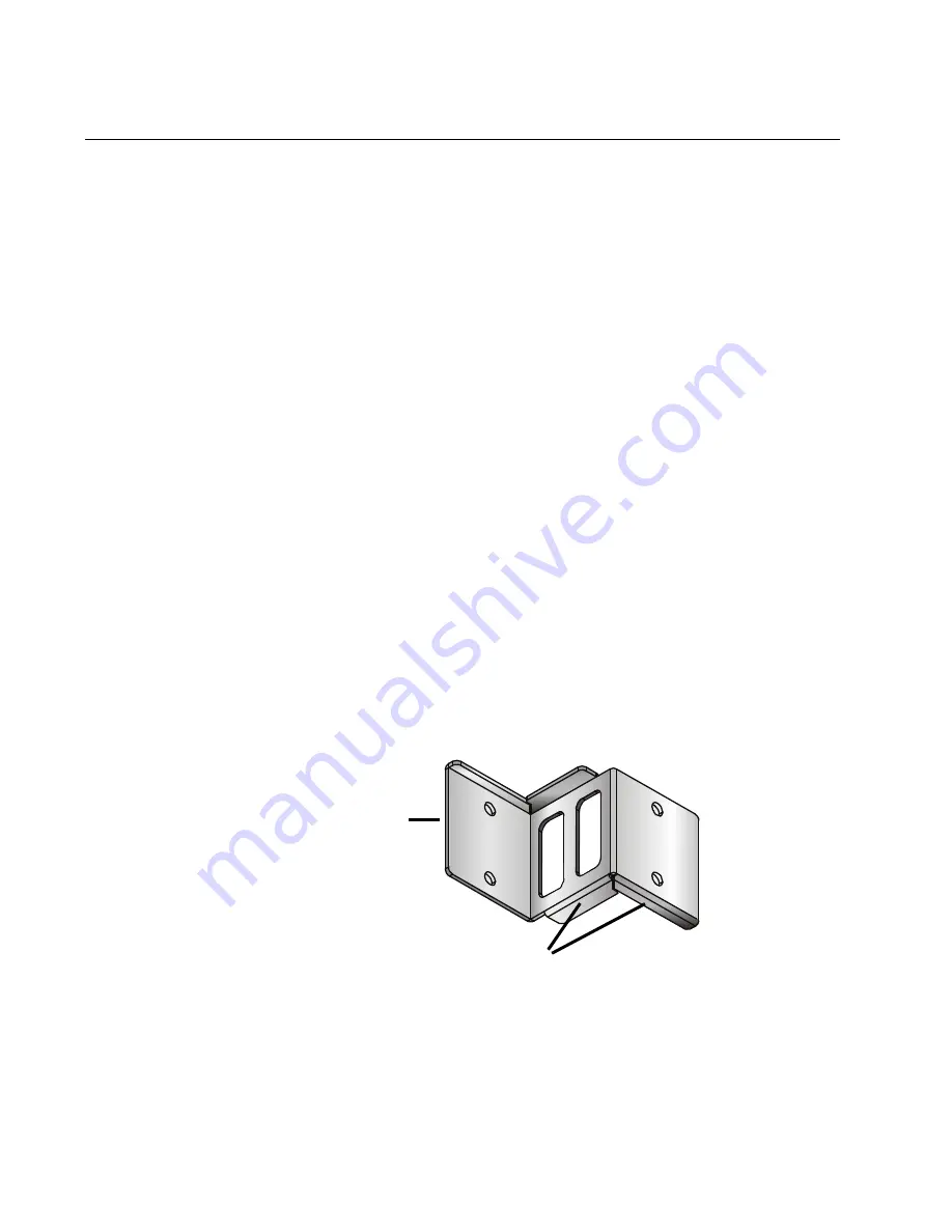
If you install the switch with the front panel facing up, the switch will
rest on the edges of the bracket, as shown in Figure 39.
F
IGURE
39. R
IDGES
ON
THE
AT-BRKT-J23
THAT
THE
SWITCH
RESTS
ON
WHEN
INSTALLED
WITH
THE
FRONT
PANEL
FACING
UP
Ridges
Attached to wall
Содержание AT-x230-10GP
Страница 10: ...viii...
Страница 14: ...4...
Страница 92: ...Chapter 2 Installation 82...
Страница 102: ...Appendix A Technical specifications 92...


