background image

10 

AT-AR256E v3 - 4 Ports ADSL2/2+ Router - Quick Setup Guide 

Front Panel  

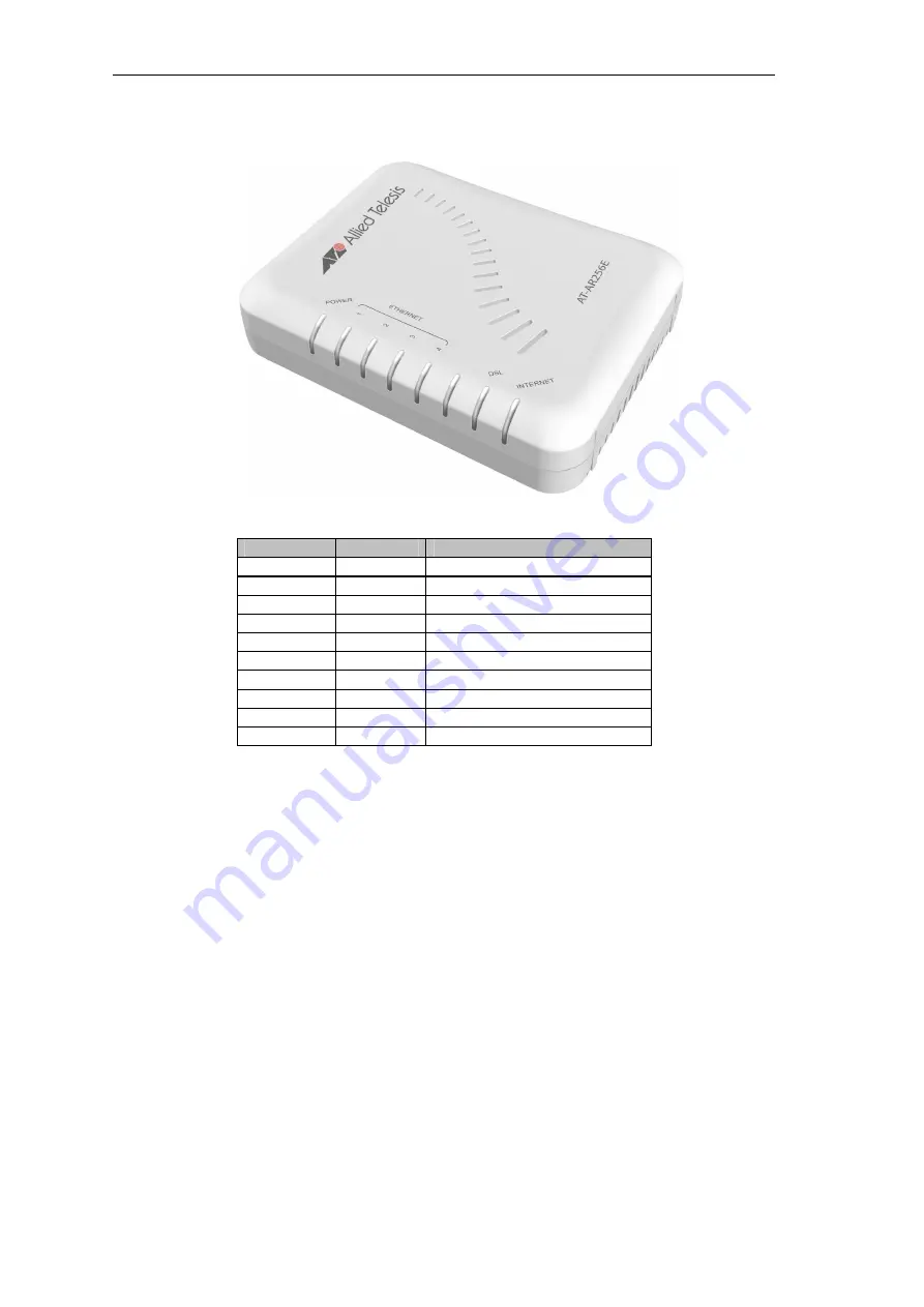
The LEDs on the front panel give you an idea about the power and connection status. 


Figure 2: LEDs on front panel 

Label 

Action 

Description 

POWER 

Off 

No power is supplied to the device 


Steady light 

Connected to a AC power supply 

ETHERNET 

Off 

No Ethernet connection 


Steady light 

Connected to an Ethernet port 


Blinking light  Transmitting/Receiving data 

DSL 

Blinking light  Establishing DSL signal  


Steady light 

DSL signal is established 

INTERNET 

Off 

No Internet connection 


Steady light 

Connected to the Internet 


Blinking light  Transmitting/Receiving data 


All manuals and user guides at all-guides.com

Содержание AT-AAR256E v3

Страница 1: ...PN 613 000821 Rev A AT AR256E v3 4 Ports ADSL2 2 Router Quick Setup Guide All manuals and user guides at all guides com a l l g u i d e s c o m...

Страница 2: ...s logos or other designations mentioned herein are trademarks or registered trademarks of their respective owners Allied Telesis Inc reserves the right to make changes in specifications and other info...

Страница 3: ...S OR LOSS INCLUDING BUT NOT LIMITED TO DIRECT INDIRECT SPECIAL WILFUL PUNITIVE INCIDENTAL EXEMPLARY OR CONSEQUENTIAL DAMAGES DAMAGES FOR LOSS OF BUSINESS PROFITS OR DAMAGES FOR LOSS OF BUSINESS OF ANY...

Страница 4: ...res Important Appendix A contains translated safety statements for installing this equipment When you see the go to Appendix A for the translated safety statement in your language Wichtig Anhang A ent...

Страница 5: ...nk 8 Chapter 1 Introduction 9 Requirements 9 Software 9 Hardware 9 Package Contents 9 Device Design 9 Back Panel 9 Front Panel 10 Chapter 2 Getting Started 11 Planning Your Network 12 Remove or Avoid...

Страница 6: ...w Chart 11 Figure 4 Sample network diagram 12 Figure 5 The POTS Splitter separates the connection for the router and telephone 14 Figure 6 Connecting the router to the computer 15 Figure 7 Connecting...

Страница 7: ...ng Started describes how to install and configure the equipment Document Conventions This guide uses several conventions that you should become familiar with before you begin to install the product No...

Страница 8: ...turn or repair must first be assigned a return materials authorization RMA number A product sent to Allied Telesis without an RMA number will be returned to the sender at the sender s expense To obtai...

Страница 9: ...ator 3 02 or higher version Firefox 5 0 or higher version Hardware 233MHz processor CD ROM Drive Ethernet network adapter Package Contents Package contents include Router Telephone cable Ethernet cabl...

Страница 10: ...plied to the device Steady light Connected to a AC power supply ETHERNET Off No Ethernet connection Steady light Connected to an Ethernet port Blinking light Transmitting Receiving data DSL Blinking l...

Страница 11: ...e flowchart below provides an outline of the steps you need to complete the installation There are brief descriptions beside each step to help you along Detailed instructions are provided in the subse...

Страница 12: ...need to avoid or remove conflicts that may interfere with the installation Probable conflicts may include Internet sharing applications Proxy software Security software TCP IP settings Internet prope...

Страница 13: ...rotocol TCP IP dialog box 7 Click OK to close the Local Area Connection Properties dialog box Configuring Internet Properties To set the Internet Properties 1 Select Start Run This opens the Run dialo...

Страница 14: ...alling a Plain Old Telephone Service POTS splitter separates the two signals and eliminates the noise Note Consult your service provider on what type of POTS Splitter should be used Figure 5 The POTS...

Страница 15: ...l be used to configure the router settings Figure 6 Connecting the router to the computer To connect the computer 1 Plug one end of the Ethernet cable from the router s ETHERNET port then plug the oth...

Страница 16: ...vices into the available Ethernet ports on your router Figure 7 Connecting other devices To connect other devices 6 Plug one end of the Ethernet cable from your computer s Ethernet port then plug the...

Страница 17: ...e router settings via the Web User Interface To open the Web User Interface 1 Open your browser 2 Enter 192 168 1 1 in the address field then press Enter This opens the Log In page 3 Enter the Usernam...

Страница 18: ...e 9 Basic Home page If the connection process has been successful the Basic Home page will contain a Disconnect button and the word Connected besides the label Internet as shown in Figure 9 If the but...

Отзывы: