


© Copyright, Alliance Laundry Systems LLC – DO NOT COPY or TRANSMIT
Operation Instructions
1800001
18
Operating Instructions
The machine is suitable for ironing linen such as
sheets, pillow cases and table linens.
Start
1. Push green "Tension" button: the circulation
pump starts to work, the burner starts.
2. Set to desired temperature.
IMPORTANT: The working temperature varies
depending on the fabric being ironed. It must be at
least 302
o
F (150
o
C) but never to exceed 365
o
F
(180
o
C).
3. Push the green "Start" button to start machine.
Green pilot comes on. Bed is pressed against
roller, exhaust is started, and roll starts to turn.
For best results, adjust speed.
Stop
1. Push red stop button, bed opens and roll stops at
once. The machine remains on temperature.
IMPORTANT: When pushing emergency stop
button, all motors and the burner are cut off and
bed opens automatically. Restarting is only possible
by resetting the emergency stop button (turn
clockwise) and pushing the power/tension button
again. Touching the finger guard will stop the roll
at once, but temperature will remain constant. To
start again, push start button.
IMPORTANT: When the finger guard is tripped
the bed remains pressed against the roll. It is
strongly recommended to start the roll as soon as
possible or to stop the machine completely.
Temperature Setting
NOTE: Set temperature to read in degrees
Fahrenheit.
SET:
Push to display the set point valve. The set point
can be changed within 3 seconds with the "UP" or
"DOWN" button. The control will automatically
switch back to normal operating mode within 3
seconds; the last entered set point sill stay in memory.
UP:
Used to increase the set point value, as well as the
parameter when in programming. Pushing the button
for several seconds will accelerate the change rate.
DOWN:
Used to decrease the set point valve, as well
as the parameter when in programming. Pushing the
button for several seconds will accelerate the change
rate.
LED "OUT":
Status light of the output. Blinks when
in set point display/change mode or during
programming.
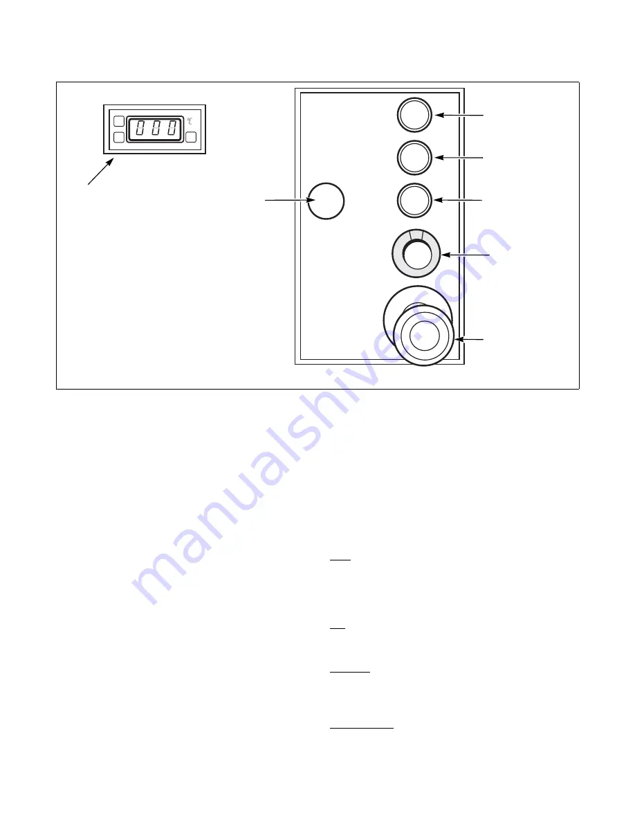
FWF50N
POWER/TENSION
ON/OFF
START BUTTON
ROLL
EMERGENCY
STOP
SPEED
ADJUSTMENT
STOP BUTTON
ROLL
GAS BURNER
OFF
TEMPERATURE
ADJUSTMENTS
Содержание UL15F069
Страница 2: ......


