TMB2242N_SVG
4
3
1
6
8
7
2
5
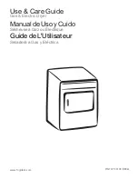
NOTE: Shaded areas indicate adjacent structure.
1.
0 in. [0 mm] minimum, 0.5 in. [13 mm] recommended between machines for removal or installation
2.
Allow 2-4 in. [51-100 mm] opening at top of machine to aid in removal or installation. A removable trim piece may be used to
conceal the opening; zero clearance allowed for trim.
3.
4 in. [100 mm] maximum header thickness
4.
Minimum clearance permitted for remainder: 12 in. [305 mm]
5.
Guard
6.
Provision for make-up air
7.
24 in. [610 mm] minimum, 36 in. [914 mm] recommended for maintenance purposes
8.
0 in. [0 mm] minimum, 0.25 in. [6 mm] recommended for removal or installation purposes
Figure 2
Position and Level the Tumble Dryer
1. Remove lint panel door, and unscrew the four shipping bolts
(one at each corner).
2. Remove tumble dryer from pallet.
NOTE: DO NOT discard shipping bolts, they are
used as machine leveling legs.
3. Remove four nuts from the literature package, and screw one
fully on to each leveling leg.
4. Screw the four leveling legs (bolts) back into the level adjust-
ing fittings from the bottom.
5. Slide tumble dryer to its permanent location. Adjust the level-
ing legs until the unit is level, or no more than 0.13 inch [3.3
mm] higher in the front. Refer to
. Tumble dryer
must not rock. Lock leveling legs with nuts previously instal-
led.
NOTE: The front of the tumble dryer should be
slightly higher than the rear (approximately 0.13
inch [3.3 mm]). This will prevent the clothes, while
tumbling, from wearing on the door glass gasket.
IMPORTANT: Keep tumble dryer as close to floor as
possible. The unit must rest firmly on floor so
weight of tumble dryer is evenly distributed.
T483I_SVG
Figure 3
Installation
©
Copyright, Alliance Laundry Systems LLC -
DO NOT COPY or TRANSMIT
23
Part No: 70457901ENR15
Содержание 0904004427
Страница 2: ......