background image

1A

OPERATIONS

HDX600-44KBTD Operating Information

TABLE OF CONTENTS

1.1

Safety Note  . . . . . . . . . . . . . . . . . . . . . . . . . . . . . . . . . . . . . . . . . . .1A-6

1.2

Operating Safety  . . . . . . . . . . . . . . . . . . . . . . . . . . . . . . . . . . . . . . .1A-6

1.3

Service Safety  . . . . . . . . . . . . . . . . . . . . . . . . . . . . . . . . . . . . . . . . .1A-7

1.4

Dimensions  . . . . . . . . . . . . . . . . . . . . . . . . . . . . . . . . . . . . . . . . . . .1A-7

1.5

Technical Data  . . . . . . . . . . . . . . . . . . . . . . . . . . . . . . . . . . . . . . . . .1A-8

1.6

Description . . . . . . . . . . . . . . . . . . . . . . . . . . . . . . . . . . . . . . . . . . . .1A-9

1.7

Before Starting . . . . . . . . . . . . . . . . . . . . . . . . . . . . . . . . . . . . . . . . .1A-9

1.8

Starting  . . . . . . . . . . . . . . . . . . . . . . . . . . . . . . . . . . . . . . . . . . . . . .1A-9

1.9

Operating . . . . . . . . . . . . . . . . . . . . . . . . . . . . . . . . . . . . . . . . . . . . .1A-10

1.10

Stopping  . . . . . . . . . . . . . . . . . . . . . . . . . . . . . . . . . . . . . . . . . . . . .1A-10

1.11

Steering  . . . . . . . . . . . . . . . . . . . . . . . . . . . . . . . . . . . . . . . . . . . . . .1A-11

1.12

Pitch Adjustment  . . . . . . . . . . . . . . . . . . . . . . . . . . . . . . . . . . . . . . .1A-11

1.13

Periodic Maintenance Schedule  . . . . . . . . . . . . . . . . . . . . . . . . . . .1A-12

1.14

Control Linkage Lubrication  . . . . . . . . . . . . . . . . . . . . . . . . . . . . . .1A-12

1.15

Lift Lever Adjustment . . . . . . . . . . . . . . . . . . . . . . . . . . . . . . . . . . . .1A-13

1.16

Transporting Trowels  . . . . . . . . . . . . . . . . . . . . . . . . . . . . . . . . . . . .1A-14

1.17

Battery Jump Start Procedures  . . . . . . . . . . . . . . . . . . . . . . . . . . . .1A-15

1.18

Greasing Thrust Bearing   . . . . . . . . . . . . . . . . . . . . . . . . . . . . . . . .1A-15

1.19

Hydraulic Preventive Maintenance  . . . . . . . . . . . . . . . . . . . . . . . . .1A-16

1.20

Caution Decals  . . . . . . . . . . . . . . . . . . . . . . . . . . . . . . . . . . . . . . . .1A-17

1.21

CE Marking  . . . . . . . . . . . . . . . . . . . . . . . . . . . . . . . . . . . . . . . . . . .1A-18

This machine is built with user safety in mind. However, it can present hazards if
improperly operated and serviced. Follow operating instructions carefully! 

If you have any questions about operating or servicing this equipment please contact
your Allen Engineering Dealer or Allen Engineering Customer Service at 800-643-0095
or 870-236-7751. 

1A-3

Содержание HDX600

Страница 1: ......

Страница 2: ...ed under one or more of the following patent numbers U S Design Patents 323 510 340 340 344 736 400 542 402 998 402 999 403 332 U S Utility Patents 4 298 555 5 108 220 5 480 257 5 480 258 5 613 801 5 685 667 5 803 658 5 816 739 5 890 833 5 934 823 6 053 660 Canadian Patents 2 039 893 French Patents 0293496 German Patents M9007736 9 With other Patents Pending Printed 01 2008 Issue Date Jan 9 2008 R...

Страница 3: ...tor abuse failure to perform normal maintenance on the product modification to product alterations or repairs made to the product without the written approval of Allen Allen specifically excludes from warranty any damage to any trowels resulting from an impact to the rotors 7 Impact damage is not covered under the Allen Gear Box warranty 8 Allen will pay shop labor on warranty items at the Allen S...

Страница 4: ... will required to specify the model number and seri al number of the unit Serial Number The serial number found on the identification plate is a six digit number The model number identifies your machine and will ensure that you receive the correct replacement parts SAMPLE 6001007001 Model Serial Location FILL IN FOR FUTURE REFERENCES Model Number ___________________ Serial Number _________________...

Страница 5: ...e Lubrication 1A 12 1 15 Lift Lever Adjustment 1A 13 1 16 Transporting Trowels 1A 14 1 17 Battery Jump Start Procedures 1A 15 1 18 Greasing Thrust Bearing 1A 15 1 19 Hydraulic Preventive Maintenance 1A 16 1 20 Caution Decals 1A 17 1 21 CE Marking 1A 18 This machine is built with user safety in mind However it can present hazards if improperly operated and serviced Follow operating instructions car...

Страница 6: ...ou this machine for Allen Engineering Certified repairs and replacement parts Place dealer information here for future reference 1A 4 DEALER NAME ___________________________________PHONE _____ ____________ ADDRESS _______________________________________________________________________ CITY _________________________________STATE ___________________ZIP ______________ SALESMAN _______________________...

Страница 7: ... to safely operate and maintain the Allen HDX600 44KBTD Model Riding Trowel For your own safety and protection from personal injury carefully read understand and observe the safety instructions described in this manual Always operate and maintain this machine in accordance with the instructions described in this manual A well maintained piece of equipment will provide many years of trouble free op...

Страница 8: ...iding Trowel Operate the machine in accordance with the manufacturer s instructions 2 Inspect your Riding Trowel for damage or tampering that can sometimes occur during shipping 3 If damage is found file a claim with your carrier immediately Mark freight bill of lading as damaged shipment 4 Do not operate Riding Trowel if any guards have been removed or if the safety switch is not operational 5 On...

Страница 9: ...ts especially in enclosed areas Fumes from fuels and solvents can become explosive and can be hazardous to your health ALWAYS operate machine with all safety devices and guards in place and in working order ALWAYS keep area around muffler free of debris such as leaves paper cartons etc A hot muffler could ignite such items starting a fire ALWAYS replace worn or damaged components with spare parts ...

Страница 10: ... Charge Hydra Drive Rotor Speed Control Foot Pedal Pilot Control Engine Speed Control Lever Style Self Locking Guard Rings Attached Operator Control Panel Multi gauge Power Retardant Spray System Capacity Pump Powered Two Nozzles 6 gal 22 7L Steering Control System Proportional Hydraulic Pilot Control w Zero Position Neutral Pitch Control Two Push Button Electro Hydraulic System Joy Stick Mounted ...

Страница 11: ...g Before starting trowel check the following Oil level in engine Hydraulic oil level Fuel level All fasteners Condition of trowel arms and blades Grease trowel daily All hydraulic hoses and fittings All linkages fulcrums etc Engine Coolant 1 8 Starting Before starting trowel be aware of all the locations and identification of controls 1 Sit down correctly on the Riding Trowel Seat DO NOT attempt t...

Страница 12: ... full RPM CAUTION After starting engine engage the throttle either 1 2 or fully This allows the engine and the hydraulic fluid to warm up faster NOTE If you start out at a low RPM this will cause the machine to have a slower response time between movement of the joysticks and the rotors CAUTION DO NOT use excessive pressure on the joysticks Excessive pressure does not increase the reaction time of...

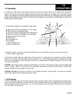
Страница 13: ...itch Adjustment Different pitch angles are needed as you work the dif ferent stages of the concrete See the drawing below When changing or setting pitch angle of trowel blades set the desired degree of pitch on the left side of the machine and then adjust the right side to match To increase the pitch press the pitch control button a which is located on top of joystick towards the inside To decreas...

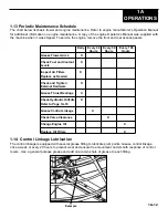
Страница 14: ...wel Arms X Check Fuel and Coolant X Levels Inspect Air Filters X Replace as Needed Check and Tighten X External Hardware Grease Thrust Bearings X Check Hydraulic Oil Filter X Refer to Page 1A 19 Grease Control Linkage X Check Valve Clearance X Change Engine Oil X Replace Oil Filters X 1 14 Control Linkage Lubrication The control linkage is equipped with several grease fitting to lubricate pivot po...

Страница 15: ...rowel arms 4 Loosen hex head cap screw A and remove it and the external star washer from the spider boss 5 Remove trowel arms from spider 5 boss with lift levers in place 6 Clean flats on trowel arm before placing it in the trowel arm jig PART 016863 7 For HDX600 series trowels use the medium spacer 1 1 4 X 2 1 2 D 8 Insert trowel arm into trowel arm jig as shown 9 Tighten socket head bolts E down...

Страница 16: ...wel 4 Turn jack handles clockwise to lift trowels and counter clockwise to lower trowel CAUTION The dolly jack lifting system is designed for short moves and to aid in servicing the trowel It is not a substitute for a towing system or trailer An optional lifting bridle M is available and recommended for lifting the trowel Attach the bridle to each of the four lifting eyes N on the trow el K M N L ...

Страница 17: ...e black to the negative terminal on the booster Attach the other end of the negative cable to your engine battery 4 Jump starting in any other manner may result in damage to the battery or the electrical system Caution Over cranking the engine can cause starter damage Allow 10 seconds for starter to cool if engaged for more than 5 seconds Caution When using lights or high amperage draw accessories...

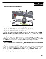
Страница 18: ...e needle on the gauge reach es 20 PSIG or is in the red then the oil filter is dirty and needs to be replaced Replace with Filter part number 048670 only NOTE Failure to use Allen Engineering replacement filters will void all hydraulic warranties Steps for Replacing Filter Remove and replace the filter 048670 B NOTE It is a common practice when replacing oil filters to replace the hydraulic oil as...

Страница 19: ...dhere to them or else serious injury can occur This decal is located next to the throttle lever on the right side of the seat frame This decal is located on the access panel for the radiator This decal is located next to the throttle lever on the right side of the seat frame This decal is located next to the control lever on the left side of the seat frame NOTE Please review the assembly drawings ...

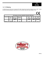
Страница 20: ...e following data was collected and is on file at AEC under test number SND07 11001 Data Summary of Sound Vibration Testing for CE Marking Test Machine Engine Avg Sound Operator Seat Foot Hand Type Pressure Ear SPL Vibration Vibration Vibration Level SPL Overall Overall Maximum dB A dB A m sec m sec m sec 44 hp HDX600 Kubota 88 5 90 9 107 9 80 3 45 4 ...

Страница 21: ...owed damage could occur which will void the warranty See below for startup procedure A When ambient temperatures are below 60 F 16 C run engine at 1 4 throttle There is an arrow A located on a decal showing where the throttle lever s front edge should be located Engage the rotors by pressing on the right foot pedal for approximately 5 to 7 minutes to allow the hydraulic system and engine system ti...

Страница 22: ... Power Unit Assembly 2 8 Dolly Jack Assembly and Accessories This machine is built with user safety in mind However it can present hazards if improperly operated and serviced Follow operating instructions carefully If you have any questions about operating or servicing this equipment please contact your Allen Engineering Distributor or Allen Engineering Corp Customer Service at 800 643 0095 or 870...

Страница 23: ......

Страница 24: ......

Страница 25: ......

Страница 26: ......

Страница 27: ......

Страница 28: ...ESS JIG DIAGRAM 24 00 60 00 60 00 W2 16 PUR W1 16 BRN A B A B TO FOOT PEDAL SWITCH FROM FUEL SOLENOID W3 16 BRN W4 16 PUR TO SEAT KILL SWITCH WIRING SCHEMATIC POWER RETURN RETURN POWER RETURN POWER VENDOR ITEM DRAWING 047545 047545 D Size Harness continued idw 06 06_ SCHEMATIC WIRE LIST AND JIG DIAGRAM 3 2 SH OF WIRE LIST WIRE LOCATION TERMINATION STRIP LENGTH REMARKS NO LG CLR SIZE I N FROM PT TO...

Страница 29: ... FTG F6400 8 8 O STR 045921 35 1 FTG F6602 6 6 6 O TEE 045924 36 1 FTG F6803 16 16 16 NWO TEE 045932 37 1 FTG F2406 16 8 O STR RDCR 045933 38 1 FTG 7574051 MAGNETIC PLUG 045948 39 1 FILTER SUCTION HEAD SSF130002 046243 40 1 FTG F2406 6 4 046289 41 1 F6804 08 08 08 NWO FLARE O FITTING 046356 42 5 FITTING F6801 6 8 NWO 046362 43 1 GV 10 SUCTION GAUGE 046242 44 1 BOX STANDARD BATTERY 046696 45 1 SIGH...

Страница 30: ... ISOL REAR NEOPRENE MOTOR MT 045757 34 1 FTG F6400 8 8 O STR 045921 35 1 FTG F6602 6 6 6 O TEE 045924 36 1 FTG F6803 16 16 16 NWO TEE 045932 37 1 FTG F2406 16 8 O STR RDCR 045933 38 1 FTG 7574051 MAGNETIC PLUG 045948 39 1 FILTER SUCTION HEAD SSF130002 046243 40 1 FTG F2406 6 4 046289 41 1 F6804 08 08 08 NWO FLARE O FITTING 046356 42 5 FITTING F6801 6 8 NWO 046362 43 1 GV 10 SUCTION GAUGE 046242 44...

Страница 31: ...0568 1 8 FSTN NUT NYLOK 10 32 029568 2 18 FSTN SFBHCS 1 4 20 x 3 4 042343 3 18 FSTN 1 4 20 PAL SNAP NUT 047546 4 1 MAIN FRAME X1 048501 5 2 CUSHION BOTTOM TANK RUBBER X1 048562 6 1 FOOT REST X1 048571 7 1 TANK FUEL ALUM F X1 048577 8 1 COVER FRONT DECK X1 048583 9 1 CUSHION TOP TANK RUBBER X1 048588 10 1 ASSEMBLY ROTOR CONTROL PEDAL X1 048594 11 1 PLATE FRONT COVER F MAINFRAME X1 048669 12 8 PLUG ...

Страница 32: ...ECALL AND MUST BE RELEASED UPON DEMAND FRAC Mainframe Hydraulic Plumbing HDX600 Riding Trowel 048522 A PR2186 AW 1 9 08 D 223 77 lbmass Parts List QTY DESCRIPTION PART ITEM 1 FTG PLUG 12 SAE 044216 1 1 FTG 7574051 MAGNETIC PLUG 045948 2 1 SIGHT GLASS SLW CL 12 SAE 046731 3 1 HOSE HS X 3 048690 4 1 HOSE HS X 4 048691 5 1 HOSE HS X 5 048692 6 1 HOSE HS X 27 048714 7 1 HOSE HS X 30 048717 8 1 HOSE HS...

Страница 33: ...OYSTICK LH SINGLE AXIS 046919 32 1 JOYSTICK RH DUAL AXIS 046920 33 3 RELAY WEATHERPROOF 047052 34 1 SEAT W SWITCH EXTRA FOAM 047200 35 1 DECAL DIESEL OVERHEAT CAUTION 047263 36 1 DECAL HOT COOLANT WARNING 047265 37 1 PLATE INSIDE F 500 SEAT FRAME 047372 38 1 GUAGE LOFA MULTI FUNCTION 047406 39 70 FSTN 1 4 20 PAL SNAP NUT 047546 40 1 LOCKING CONTROL QUADRASTAT Q14020 047643 41 3 BUMPER RUBBER F SEA...

Страница 34: ...ER F SEAT PLATE STOP 047665 42 1 HOURMETER SENDEC 807 204 0111 047685 43 1 DECAL ACE LARGE OVAL 048036 44 1 DECAL ACE SMALL OVAL 048037 45 1 DECAL CALIFORNIA PRPSTN 65 048181 46 1 ARMREST WITH PIVOT LH 048237 47 1 ARMREST WITH PIVOT RH 048238 48 1 BRACKET LH ARMREST MOUNT 048240 49 1 BRACKET RH ARMREST MOUNT 048241 50 2 CLAMP 22 HOSE 048352 51 1 SEAT FRAME X1 RIDING TROWEL 048544 52 1 TANK VENT X1...

Страница 35: ...3 29 1 BRACKET FAN MOUNT TO COOLER HD530 045866 30 1 AIR OIL COOLER C 20 046238 31 1 JOYSTICK LH SINGLE AXIS 046919 32 1 JOYSTICK RH DUAL AXIS 046920 33 3 RELAY WEATHERPROOF 047052 34 1 SEAT W SWITCH EXTRA FOAM 047200 35 1 DECAL DIESEL OVERHEAT CAUTION 047263 36 1 DECAL HOT COOLANT WARNING 047265 37 1 PLATE INSIDE F 500 SEAT FRAME 047372 38 1 GUAGE LOFA MULTI FUNCTION 047406 39 70 FSTN 1 4 20 PAL ...

Страница 36: ...ER 5 8 18 043269 26 2 FTG F6400 4 6 O 045922 27 4 FTG F6801 4 6 NWO 90 ELB 045923 28 1 CAP PRESSURE PLATE 047187 29 1 FSTN HHCS 5 8 18x2 1 4 GR8 YZPLT 047354 30 2 FSTN HHCS 5 8 18 x 3 GR 8 048339 31 2 BEARING ASSEMBLY F ROTOR MOUNT X1 048561 32 1 MOUNT LH HYD MOTOR X1 048611 33 1 CROSSHEAD WELDMENT X1 048622 34 2 CHANNEL STEERING CONNECTOR X1 048624 35 4 SPACER STEERING CYLINDER X1 048627 36 1 PIN...

Страница 37: ...TF STR GREASE 201163 9B LH SOM Rotor Assembly Parts List QTY DESCRIPTION PART ITEM 4 FSTN HHCS 3 8 16 X 1 010036 1 4 FSTN LW 3 8 010091 2 8 FSTN FW HARDENED 1 2 011490 3 2 FSTN RING RETAINING E CLIP 015677 4 3 FSTN NUT HEX JAM 5 8 18 RH 020688 5 1 FSTN HHCS 5 8 18 X 2 GR 8 027969 6 2 FSTN HHCS 1 2 13 X 1 1 2 GR8 037798 7 6 FSTN HHCS 1 2 13 X 1 1 4 GR 8 038508 8 8 FSTN NUT STOVER LOCK 1 2 13 040208...

Страница 38: ... ROD END 5 8 FEMALE 043125 22 7 FSTN NUT STOVER 5 8 18 043269 23 2 FTG F6400 4 6 O 045922 24 2 FTG F6801 4 6 NWO 90 ELB 045923 25 1 CAP PRESSURE PLATE 047187 26 1 FSTN HHCS 5 8 18x2 1 4 GR8 YZPLT 047354 27 1 MOUNT RH HYD MOTOR X1 048618 28 1 CHANNEL STEERING CONNECTOR X1 048624 29 2 SPACER STEERING CYLINDER X1 048627 30 1 PIN YOKE ARM 048628 31 1 FSTN HHCS 5 8 18 x 2 3 4 GR 8 048629 32 1 ARM YOKE ...

Страница 39: ...LUG PLASTIC CAP EC12 015693 2 1 SCR 1 2 13 X 1 1 2 LH SHCS 020155 3 1 WASHER RETAINING HD 037652 4 1 BEARING BALL THRUST EW2 039685 5 1 PLATE SHD PRESSURE 039687 6 1 SPIDER ASSY 1200 5 SHD RH SOM 040795 7 1 CAP PRESSURE PLATE 047187 8 1 FITTING 1 8 27 PTF STR GREASE 201163 9 RH SOM Rotor Assembly Parts List QTY DESCRIPTION PART ITEM 1 FSTN HHCS 1 2 13 X 1 1 2 010069 1 7 FSTN FW HARDENED 1 2 011490...

Страница 40: ...TEER MANIFOLD X1 048636 23 1 MUFFLER X1 048639 24 1 RADIATOR X1 RIDER 048649 25 1 KIT RADIATOR MOUNT BRACKETS 048650 26 1 FAN PUSHER F X1 048651 27 1 MANIFOLD STEERING X1 048656 28 1 PUMP AUXILLARY X1 048658 29 1 PUMP PISTON X1 HYDRAULICS 048663 30 1 HOUSING AND COUPLING KUBOTA 05 X1 048679 31 1 BRACKET RAD SUPPORT X1 048744 32 1 ELBOW MODIFIED SAMCO SPORT 048797 33 Hoses and Fittings Parts List Q...

Страница 41: ...ATION AND MUST NOT BE DISCLOSED WITHOUT PERMISSION PRINTS ARE SUBJECT TO RECALL AND MUST BE RELEASED UPON DEMAND FRAC ASSEMBLY DOLLY JACK HDX600 RIDING TROWEL SEE BOM 048770 X 2 2186 250 TDG 2 7 07 APPROVAL USED ON D TYPE SIZE MST Tol CLASS PARTS LIST QTY DESCRIPTION PART ITEM 2 FSTN LW 3 8 010091 1 2 PIN Ø3 16 X 2 ZP STL COTTER 010133 2 2 FSTN HHCS 3 8 16 X 2 GR 8 026775 3 2 SPACER SP DOLLY JACK ...

Отзывы: