Installation Instructions
Original Instructions
Prosafe Electronic Time Delay Unit
Catalog Numbers 440T-MSTUE
x
, 440T-MDTUE
x
Summary of Changes
This publication contains new and updated information regarding the
Prosafe® Electronic Time Delay Units as indicated in the following table.
Installation must be in accordance with the following steps and stated
specifications and implemented by suitably competent personnel. This
device is intended to be part of the safety-related control system.
Before installation, perform a risk assessment to determine whether the
specifications of this device are suitable for all foreseeable operational
and environmental characteristics of the machine to which it is to be
fitted.
At regular intervals during the life of the unit, check whether these
characteristics foreseen remain valid. Inspect this device for evidence of
accelerated wear, material degradation, or tampering. If necessary,
replace the device. The manufacturer cannot accept responsibility for a
failure of this device if the procedures are not implemented or if it is
used outside the recommended specifications.
Adherence to the recommended maintenance instructions forms part of
the warranty.
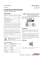
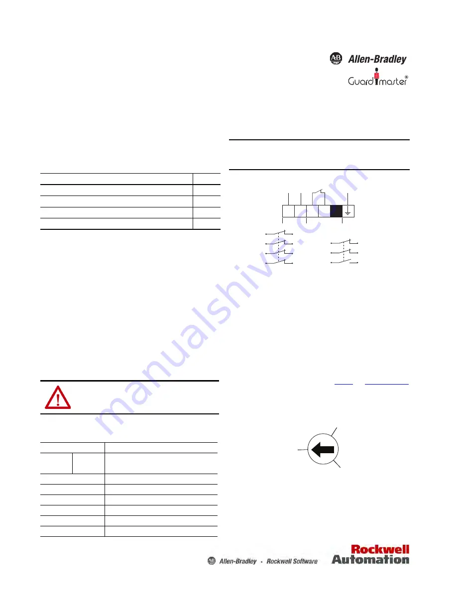
Figure 1 - Wiring Diagram (Shown with Power On)
EMD Safety Relay
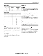
The EMD safety relay has two switches. The combination of the switch
settings determines the functionality and the duration. During
configuration, the Time switch determines the duration of the range
switch.
To configure, power the unit OFF. Set the range switch to zero and the
time switch to either 1 (for short range timing) or 10 (for long range
timing). Apply power and adjust the time and range switches, as
necessary. Due to intended operation of this unit, only on-delay range
settings 5, 6, and 7 can be used. After adjusting the switches, cycle the
power to the unit to store the settings. See
Table 3
and
Table 4 on page 3
for Range and Time Switch Adjustments.
SI Safety Relay
The SI safety relay is set to AM (automatic reset) at the factory. Verify
that it is still set to AM. Do not change this setting.
Topic
Page
Added EMD Safety Relay section
1
Replaced Logic Setting section with SI Safety Relay
1
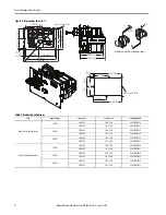
Adjustments to dimensional drawings
2
New Time and Range Setting tables
3
WARNING:
Do not defeat, tamper, remove, or bypass this unit.
Severe injury to personnel could result.
Table 1 - General Specifications
Attribute
440T-MSTUEx, 440T-MDTUEx
Safety contacts
Isolator on
(STUE and
DTUE)
3 N.O. Safety (40 A) + 1 N.O. (20 A)
2 N.O. Safety (20 A) + 1 N.C. (20 A)
Solenoid monitor switch
1 N.C. Safety (10 A)
Input voltage
24V DC (6.5 W)
Mechanical life
100,000 (typical)
Shear force to key, maximum
15.1 kN (3398 lbs)
Torque to key, maximum
14 N•m (10.12 lb•f)
Operating temperature
-10…+40 °C (14…104 °F)
IMPORTANT
The safety contacts of these products are described as normally
closed (N.C.). For example, with the guard closed and the
actuator in place (where relevant), the machine is able to start.
Solenoid Monitor
Signal Input
+
-
1
3
5
13
2 (40A)
4 (40A)
6 (40A)
14 (20A)
1
3
7
2 (20 A)
4 (20 A)
8 (20 A)
Safety
Safety
Safety
Safety
STUE 10, 20, 30, DTUE 10, 20, 30
STUE 11, 22, 33, DTUE 11, 22, 33
RESET
0
MM
AM

