English-19
Refer to the PowerFlex 40P User Manual supplied with the drive for
complete listing of parameters.
To clear a fault, press the Stop key, cycle power or set A100 [Fault Clear] to 1 or
2.
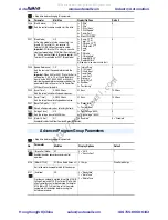
Enhanced Program Group Parameters
= Stop drive before changing this parameter.
No.
Parameter
Min/Max
Display/Options
Default
E216
[Motor Fdbk Type]
0/5
0 = “None”
1 = “Pulse Train”
2 = “Single Chain”
3 = “Single Check”
4 = “Quadrature”
5 = “Quad Check”
0
Selects the encoder type.
E217
[Motor NP Poles]
2/40
1
4
Defines the number of poles in the motor.
E218
[Encoder PPR]
1/20000
1
1024
Specifies the encoder pulses per revolution when
an encoder is used. For additional information refer
to Appendix F of the PowerFlex 40P User Manual.
Program Group Parameters
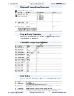
Advanced Display Group Parameters
No.
Parameter
Min/Max
Display/Options
d301 [Drive Status 2]
0/1
1
d302 [Fibers Status]
0/1
1
d303 [Slip Hz Meter]
0.0/25.0 Hz
0.1 Hz
d304 [Speed Feedback]
0/64000 RPM
1 RPM
d305 [Speed Feedback F]
0.0/0.9
0.1
d306 [Encoder Speed]
0/64000
1
d307 [Encoder Speed F]
0.0/0.9
0.1
d308 [Units Traveled H]
0/64000
1
d309 [Units Traveled L]
0.00/0.99
0.01
d310 [Fault 4 Code]
0/122
1
d311 [Fault 5 Code]
0/122
1
d312 [Fault 6 Code]
0/122
1
d313 [Fault 7 Code]
0/122
1
d314 [Fault 8 Code]
0/122
1
d315 [Fault 9 Code]
0/122
1
d316 [Fault 10Code]
0/122
4
Fault Codes
No.
Fault
Description
F2
Auxiliary Input
(1)
Check remote wiring.
Verify communications programming for intentional fault.
F3
Power Loss
Monitor the incoming AC line for low voltage or line power interruption.
Check input fuses.
F4
UnderVoltage
(1)
Monitor the incoming AC line for low voltage or line power interruption.
F5
OverVoltage
(1)
Monitor the AC line for high line voltage or transient conditions. Bus overvoltage can also be
caused by motor regeneration. Extend the decel time or install dynamic brake option.
Aotewell Ltd
www.aotewell.com
Industry Automation
HongKong|UK|China
+86-755-8660-6182
http://www.aotewell.com/
All manuals and user guides at all-guides.com


