


2
Rockwell Automation Publication 442G-DM001A-EN-P - September 2015
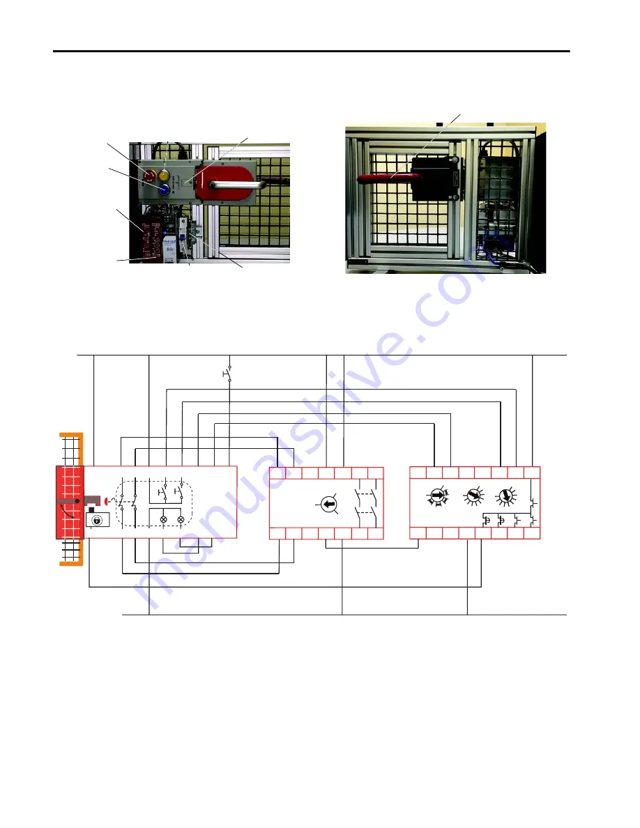
Multifunctional Access Box and Guard Locking with Time Delay Safety Relay
System Setup
Wiring Diagram
Description of Operation
1.
Turn Power ON by plugging in to 120V AC.
Be sure that the circuit breaker is switched to the on position.
2.
Check that the guard door is closed and locked.
When the door is closed and locked, both push buttons are
illuminated.
Yellow Push Button -
Unlock Request
On/Off Circuit
Breaker
Manual Release
Green Power Reset
Button (800F)
Blue Push Button -
Reset
GLT relay Relay
Logic = 2
Range = 3
Time = 6
SI Relay Automatic/
Manual Reset (AM)
E-stop
Front View
Rear View
Escape Release
A2
S12 S22
24
51 L61
B2
L12 L11
14
A1
S11
440R-GL2S2T
S21
S44
S54
Y32
LOGIC
RANGE
TIME
1
2
3
4
5
6
7
8
10
9
0
1
2
3
4
5
6
7
8
9
0
1
2
3
4
5
6
7
8
9
S11
S12
S21
S22
S34 A1 13
L11 A2
14
23
24
Y32
440R-S12R2
RESET
0
MM
AM
4.4
4.6
RST
4.5
2.7
3.3
3.1
3.2
UB
UA
0V
3.7
OT
5.2
OL
5.3
MAB
2.4
2.3
2.2
2.1
Reset and Lock Request
Guardlocking Unlock Request
Safety
Gate
Open
Close
MAB Fault Reset
Safety Out A
Safety Out B
OT = Gate Closed and Bolt Extended; not Locked
OL = Gate Closed, Bolt Extended and Locked
Guardlocking Solenoid Lock / Unlock Command
SI
GLT
24V DC
24V DC COM