


8
FLEX I/O 48V DC Digital Input and Output Modules
Publication 1794-IN105C-EN-P - July 2018
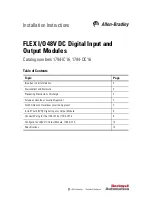
Install Your 48V DC Digital Input or Output Module
The module mounts on a 1794 terminal base.
1. Rotate the keyswitch (3) on the terminal base (4) clockwise to position 4 as
required for this type of module.
2. Make sure the FlexBus connector (1) is pushed all the way to the left to connect
with the neighboring terminal base/adapter.
You cannot install the module unless the connector is fully extended.
3. Make sure the pins on the bottom of the module are straight so they will align
properly with the connector in the terminal base.
4. Position the module (7) with its alignment bar (6) aligned with the groove (5) on
the terminal base.
5. Press firmly and evenly to seat the module in the terminal base unit. The module
is seated when the latching mechanism (2) is locked into the module.
Description
Description
1
FlexBus connectors
5
Groove
2
Latching mechanism
6
Alignment bar
3
Keyswitch
7
Module
4
Terminal base
6
1
7
5
4
3
2
45284


