Rockwell Automation Publication 6300B-UM002A-EN-P - October 2020
19
Chapter 2 Install the Wall Mount Box PC
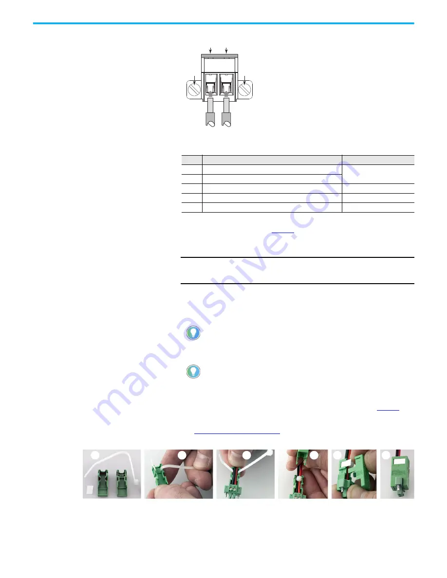
Table 1 - DC Terminal Block Connection Specifications
6. Tighten the screws on top of the terminal block to secure the DC power
wires to the torque value in
.
7. Slide the connector half with the attached tie onto the end of the DC
terminal block (C).
8. Tighten the cable tie so it is snug against the terminal wires.
9. Use cutting pliers to cut the excess part of the cable tie (D).
10. Install the white label supplied with the kit (E).
11. Align and install the other connector clamp half to complete the
assembly (F).
12. Reconnect the DC terminal block with the connector assembly to the
computer chassis.
Torque the DC terminal block flange screws to the values in
13. Turn on the main power switch or breaker.
14. See
for what happens during initial
computer power-up.
Item
Description
6300P-PBCx Models
1
DC+ (24V DC nominal) recommended power wire size
2.5 mm
2
(14 AWG)
2
DC- (0V DC) recommended power wire size
3
Stripped wire length
7 mm (0.275)
4
Torque range to secure DC power wires
0.5...0.6 N•m (0.37...0.4 ft•lb)
5
Torque value to reinstall DC terminal block to computer
0.3 N•m (0.22 ft•lb)
IMPORTANT
The DC terminal block in the photos is only for illustrative
purposes. Your DC terminal block can differ in size, shape, and
color to what is shown in the photos.
The white label can be used for identification or other information.
When installed correctly, both clamp tabs snap into place.
Cat. Nos. 6300B-PBCx Wall Mount PCs
DC Terminal Block (Green)
1
2
3
3
4
5 (M3)
5 (M3)
4
D
A
B
C
E
F


