


C
ONFIGURATION
A
PPENDIX
N
EXUS
M
ULTIPLEXOR
&
C
ONTROLLER
U
SER
G
UIDE
DOC.
CONTROL
#8102548-000
REV
01
2
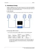
2. Hardware Setup
Multiplexors,
ALX-2525
, receive control signals and power from the MUX controller,
ALX-2530.
The MUX controller sources power from either the ALR-F800 series reader USB Host port, the
ALR-F800 GPIO +12VDC through the DB15 connector or an external power supply. Power source
is determined by jumper inside of the MUX controller.
2.1. Block Diagram
The physical interface between controller, MUX and reader is depicted in the example below:
2.2. Powering the MUX Controller
2.2.1. There are 3 ways to power the MUX controller as shown in the table below:
Options
F800 Power
GPIO DB15
Cable
USB Cable
Ext AC/DC
Power Supply
USB +5V
PoE or AC/DC* Required
Required
N/A
GPIO +12V AC/DC*
Required
N/A
N/A
Ext 6-24V
PoE or AC/DC* Required
N/A
Required
* To comply with FCC requirements, when using the +12 VDC AC/DC power supply, you
must use the Alien su12 VDC AC/DC power supply. If this power supply does
not include a ferrite installed near the DC jack you must order and install Alien Model
ALX-2040 ferrite to it
Содержание Nexus ALX-2525
Страница 1: ...Nexus Multiplexor Controller ALX 2525 ALX 2530 User Guide Nexus Multiplexor Controller ...
Страница 4: ......