1
ALI-NVR5332P_SQ
191025
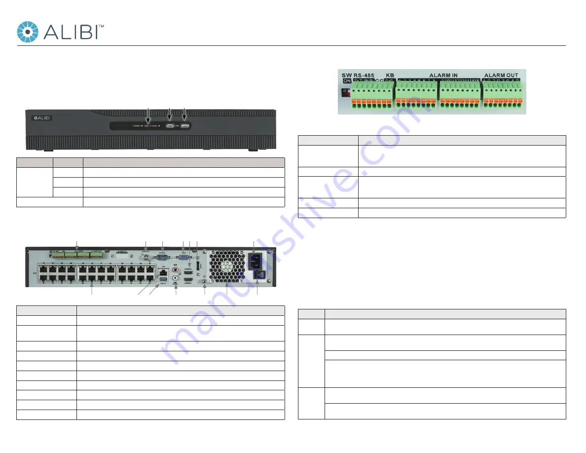
RS-485, ALARMS IN/OUT
RS-485, Alarm IN / OUT terminations
Item
Description
SW ON
RS-485 termination switch:
Up position is not terminated.
Down position is terminated with 120 Ω resister.
RS-485 (T+, T-, R+. R-)
T+ and T- pins connect to R+ and R- pins of PTZ receiver respectively.
KB
Controller port:
D+, D- pin connects to Ta, Tb pin of controller.
For cascading devices, the first NVR’s D+, D- pin should be connected with the D+, D- pin of the next NVR
ALARM IN (1 through 16)
Alarm inputs 1 - 16. Alarm input is tied to ground through the alarm sensor.
ALARM OUT (1-G through 4-G)
Alarm outputs 1 - 4 with ground terminations.
Mouse Control
A standard 3-button (left/right/scroll-wheel) USB mouse can also be used with this NVR. To use a USB mouse:
1.
Plug USB mouse into the either the front panel or backpanel USB connector of the NVR.
2.
The mouse will be automatically detected. If the mouse is not detected, the mouse may not be compatible with the NVR. Please refer
to the recommended device list from your provider.
The operation of the mouse:
Action
Effect
Right click
Live view
: Show menu.
Menu: Exit current menu to upper level menu.
Left click
Single click
: Live view: Select channel and show the quick set menu.
Menu
: Select and enter.
Double click
: Live view: Switch between single-screen and multi-screen.
Click and drag
: PTZ control: pan, tilt and zoom.
Tamper-proof, privacy mask and motion detection
: Select target area.
Digital zoom-in
: Drag and select target area.
Live view
: Drag channel/time bar
Scroll wheel
Scroll up
: Live view: Previous screen.
Menu
: Previous item.
Scroll down
: Live view: Next screen.
Menu
: Next item.
This quick setup guide provides instructions to initially setup and use the ALI-NVR5332P network video recorder (NVR). For additional
information on the extensive capabilities of your NVR, refer to the
ALIBI™ Embedded Network Video Recorder Firmware V4.21.005 (or
later) User Manual
provided by your vendor.
NVR Front Panel
Status
indicators USB ports (2)
Item
Function / Description
Status Indicators
POWER
Indicator is green when the unit is powered on. When the unit is off, the LED is red if power is available.
HDD
HDD indicator blinks red when data is being read from or written to an HDD.
TX/RX
Blinks green when the network connection is functioning normally.
USB Interfaces
Universal Serial Bus (USB) ports for additional USB devices such as a mouse or Hard Disk Drive (HDD).
NVR Backpanel
Camera Channels (24, with POE) LAN
RS-485, Alarms IN / OUT
Power connector
Fan outlet ON / OFF switch
RS-232, Monitor Out (BNC, VGA, HDMI), eSATA
Audio IN / OUT Ground
USB 3.0
Item
Description
RS-232 Interface
DB9 (male) connector for RS-232 devices
VIDEO OUT (VGA, HDMI1, 2),
eSATA
See Specifications section
AUDIO IN / OUT
RCA connector for Line level audio input and output.
RS-485, ALARMS IN/OUT
See below.
POWER CONNECTOR
AC 100 V ~ 240 V power supply.
ON / OFF Switch
Switch for powering the device on or off.
GROUND
Terminal for ground. Connect to earth ground before powering on the NVR.
LAN Interface
10/100/1000BASE-T Ethernet network interface
USB interface
Universal Serial Bus (USB) 3.0 port for additional devices such as USB mouse and USB Hard Disk Drive (HDD).
Internal Ethernet switch ports
24 ports for IP cameras. These ports provide Power over Ethernet (PoE) to the cameras.
ALI-NVR5332P Embedded Network Video Recorder Quick Setup Guide


