


3
www.Observint.com
© 2015 Observint Technologies. All rights reserved.
Step 2. Connecting it together – initial system setup
1.
Plug the LAN cables from the cameras into the POE RJ45 connectors on the back of the NVR.
If other cameras to be monitored by the NVR will network to it through the LAN, plug their Ethernet cables into a switch (router) on
the LAN and power on those cameras. (Power to other cameras on the LAN may be provided through a PoE switch if the camera is PoE
capable, or through a separate cable and power adapter).
2.
Power on the NVR using the power on / off (I / O) switch on the back panel.
3.
Power on the monitor.
NOTE
Some monitors have multiple inputs such including VGA ,HDMI, BNC, etc. If you are using this kind of monitor, configure your monitor to
display the input connected to your NVR (HDMI or VGA).
Step 3. Using the Wizard for basic configuration setup
1.
Power on the NVR. Normally, an Alibi logo splash screen appears within 2 minutes. A secondary flash screen will appear showing the
status of the HDDs installed in the NVR.
After the Alibi splash screen appears (see above), the NVR will check the status of HDDs installed within the chassis, and show the
show icons on the screen indicating their status. A green check mark on the icon indicates that the associated HDD is operating
normally. If you installed new (or uninitialized) HDDs in the chassis before running the Wizard, those HDDs must be initialized before
use. HDD initialization can be performed within the wizard and within the firmware menu system.
Following the splash screen, a monitor resolution screen may appear. Open the drop down list and select the monitor resolution you
prefer, then click
OK
.
2.
The Setup Wizard can assist you in making important configuration settings in DVR. Click
Next
button on the Wizard window to open
the
Login
window.
NOTE
The configuration settings presented in the setup Wizard can also be made and changed using the Menu system. Refer to the
ALI-NVR5100P
Series Embedded Network Video Recorder User Manual
provided electronically with your system.
3.
Locate the jumper associated with the alarm output you are using for an AC load alarm, then remove it. Save the jumper for use later,
if needed.
4.
Reinstall the NVR top cover.
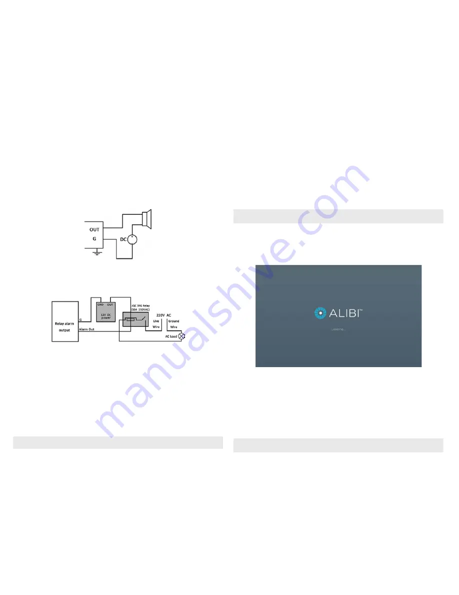
DC load alarm output circuits
DC loads must operate within the limitation of 12V/1A. To connect to a DC alarm output, use the following diagram:
NVR
DC LOAD
AC load alarm output circuits
To connect an AC load to an alarm output, a jumper, associated with the output on the alarm termination PC board, (within the chassis), must
be removed. These jumpers shunt pin pairs J1, J2, J3, and J4 for alarm outputs 1, 2, 3, 4 respectively. Use an external relay for safety.
NVR
1.1 Install a monitor, mouse, power
For the following steps, refer to the back panel photo above for the location of connectors.
1.
Install and setup your monitor in accordance with the instructions provided with the monitor. Do not power it on at this time.
2.
Cable the HDMI or VGA connector to your monitor’s VGA or HDMI input. The HDMI interface provides the best performance.
3.
Plug the mouse into the USB connector on the front or back of the NVR.
4.
If you plan to access your NVR remotely, or configure your NVR to transmit alerts, email, etc. to external servers, plug a drop cable from
your local area network (LAN) into the RJ45 LAN connector on the back of the NVR.
5.
Connect the power cord to the power connector on the back panel of the NVR, and then into a UPS (preferred) or surge protector.
NOTE
Do not power on the NVR at this time.


