background image

31

ALI-NVR5000P Embedded NVR User Manual

b.  In the 

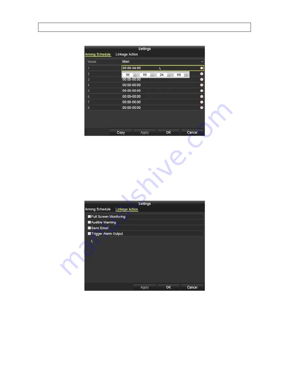
Arming Schedule

 tab, you can define up to eight periods for each day. The periods must not overlap. 

c.  Click the down arrow in the Mon field (see above) to setup the schedule for a different day, and/or click 

Copy

 to copy the 

Arming Schedule you setup in the window to other days of the week. 

d.  Click 

Apply

 to save the settings. 

e.  Click the 

Linkage Action

 tab. In this tab, you can cause certain actions to occur when video loss occurs. 

f.  Select the actions you want to occur, then click 

Apply

 to save your settings, and 

OK

 to return to the 

Video Loss

 menu. 

The 

Notify Surveillance Center

 and 

Send Emai

l options require additional network settings. 

4.  In the 

Video Loss

 menu, click 

Apply

 to save your settings for this camera. 

SECTION 2: INSTALLING THE SYSTEM

Содержание ALI-NVR5000P Series

Страница 1: ...er Manual Products ALI NVR5016P ALI NVR5032P ALI NVR5000PSeriesNetworkVideoRecorder PLEASE READ THIS MANUAL BEFORE USING YOUR SYSTEM and always follow the instructions for safety and proper use Save this manual for future reference ALI NVR5016P_SM 7 17 14 ...

Страница 2: ...smission or broadcast of any person s voice without their consent or a court order is strictly prohibited by law Observint makes no representations concerning the legality of certain product applications such as the making transmission or recording of video and or audio signals of others without their knowledge and or consent We encourage you to check and comply with all applicable local state and...

Страница 3: ...ollowing tips Ensure unit is installed in a well ventilated dust free environment Unit is designed for indoor use only Keep all liquids away from the device Ensure environmental conditions meet factory specifications Ensure unit is properly secured to a rack or shelf Major shocks or jolts to the unit as a result of dropping it may cause damage to the sensitive electronics within the unit Use the d...

Страница 4: ... Protect the power cord from being stepped on or pinched particularly at plugs and the points where they exit from the apparatus Do not drop metallic parts through slots This could permanently damage the appliance Turn the power off immediately and contact qualified service personnel for service Handle the appliance with care Do not drop or shake as this may damage the device Do not expose the app...

Страница 5: ...larm outputs to the NVR 12 2 4 Install a monitor mouse power 13 2 5 Connecting it together initial system setup 14 2 5 1 Using theWizard for basic configuration setup 14 2 6 Access the Menu system 21 2 7 Customize camera configurations 22 2 7 1 Camera OSD setup 23 2 7 2 Camera Image setup 23 2 7 3 Camera PTZ setup 24 2 7 4 Camera Motion detection setup 24 2 7 5 Camera Privacy Mask setup 27 2 7 6 C...

Страница 6: ...Status icons 59 4 2 Quick SettingToolbar 59 4 3 LiveView pop up menu 61 4 3 1 LiveView settings 61 4 4 Channel Zero Encoding 63 SECTION 5 PTZ Controls 64 5 1 Configuring PTZ settings 64 5 2 Setting PTZ presets patrols and patterns 65 5 2 1 Customizing Presets 65 5 2 2 Calling Presets 66 5 2 3 Customizing Patrols 67 5 2 4 Calling Patrols 68 5 2 5 Customizing Patterns 69 5 2 6 Calling Patterns 70 5 ...

Страница 7: ...l 101 6 2 11 Digital Zoom 102 6 3 Backing up Record Files Export 103 6 3 1 Quick Export 103 6 3 2 Export by video search 105 6 3 3 Export by Event Search 108 6 3 4 ExportingVideo Clips during playback 110 SECTION 7 Managing User Accounts 115 7 1 Adding a user account 115 7 2 Deleting a user account 119 7 3 Editing a user account 119 7 3 1 Edit admin user 120 SECTION 8 Network Settings 122 8 1 Conf...

Страница 8: ...work Statistics 145 9 6 6 HDD Detect 146 9 7 Hot Spare device backup 148 9 7 1 Identifying the Hot Spare device 149 9 7 2 Setting theWorking device 149 9 7 3 Managing Hot Spare System 150 9 8 Configuring Disk Clone 152 SECTION 10 Remote Access 154 10 1 Remote login 154 10 2 Remote LiveView screen 157 10 3 Remote Playback screen 159 10 4 Remote Log screen 161 10 5 Remote Configuration screen 162 SE...

Страница 9: ...ew Quick setting menu Motion detection video tampering video exception alert and video loss alert functions Privacy mask Zooming in by clicking the mouse and PTZ tracing by dragging mouse HDD Management Supports up to 4 internal SATA hard disk drives with a maximum of 4TB storage capacity in each drive 8 network disks 8 NAS disks or 7 NAS disks 1 IP SAN disk can be connected Supports HDD S M A R T...

Страница 10: ...etection tampering abnormal signal video input output standard mismatch illegal login network disconnected IP confliction abnormal record capture HDD error and HDD full etc Alarm triggers full screen monitoring audio alarm notifying surveillance center sending email and alarm output Automatic restore when system is abnormal Other Local Functions Operable by front panel mouse remote control and con...

Страница 11: ...t and shutdown RS 232 RS 485 transparent channel transmission Alarm and exception information can be sent to the remote host Remotely start stop recording Remotely start stop alarm output Remote PTZ control Remote JPEG capture Virtual host function is provided to get access and manage the IP camera directly Two way audio and voice broadcasting Embedded WEB server 1 1 NVR Controls connectors and in...

Страница 12: ...e up and down button can adjust the level bar of the image parameters In live view mode these buttons can be used to switch channels ENTER The Enter button is used to confirm selection in menu mode or used to check checkbox fields and ON OFF switch In playback mode it can be used to play or pause the video In single frame play mode pressing the Enter button will play the video by a single frame In...

Страница 13: ... Upper and lowercase alphabet symbols or numeric input Press the button twice to switch the main and auxiliary output JOG SHUTTLE Control Move the active selection in a menu It will move the selection up and down In Live View mode it can be used to cycle through different channels In the Playback mode it can be used to jump 30s forward backward in video files In PTZ control mode it can control the...

Страница 14: ...tor for audio output This connector is synchronized with CVBS video output VGA AUDIO OUT BNC connector for audio output This connector is synchronized with VGA video output Internal Ethernet switch ports 16 ports for IP cameras These ports provide Power over Ethernet PoE to the cameras RS 485 ALARMS IN OUT Item Description SW ON RS 485 termination switch Up position is not terminated Down position...

Страница 15: ...rol mode it is used to zoom out the image 10 MENU button Press the button will help you return to the Main menu after successful login Press and hold the button for 5 seconds to turn off audible key beep In PTZ Control mode the MENU WIPER button will start wiper if applicable 11 PREV button Switch between single screen and multi screen mode In PTZ Control mode it is used to adjust the focus in con...

Страница 16: ...ouse can also be used with this NVR To use a USB mouse 1 Plug USB mouse into the either a front panel or backpanel USB connector of the NVR 2 The mouse will be automatically detected If the mouse is not detected the mouse may not be compatible with the NVR Please refer to the recommended device list from your provider The operation of the mouse Action Effect Right click Live view Show menu Menu Ex...

Страница 17: ...ed while in the numeric keyboard The alphanumeric keyboard is shown in the following picture Some control keys toggle their function when they are clicked A numerical keyboard shown beneath appears for numerical entries such as an IP address Uppercase Lowercase Backspace Switch to numeric Enter Softkeyboard alphanumeric Switch to symbols Backspace Switch to alphanumeric Enter Softkeyboard numeric ...

Страница 18: ...re the following items not included with your system components VGA or HDMI compatible computer monitor IP cameras and cables compatible with the NVR Tools to install the cameras and route power and video cables Fasteners to attach the cameras to the mounting surfaces A display device to connect to the NVR The NVR will connect directly to a VGA video monitor or an HDMI monitor HDMI cable is provid...

Страница 19: ...l block airflow through the unit Uninterruptible power supplies It is strongly suggested that power to the system be routed through an uninterruptible power supply UPS These devices will keep your security system running through most power outages in addition to providing excellent surge and sag protection The UPS should support the NVR and all cameras to ensure normal operation during abnormal po...

Страница 20: ...nects to the RS 485 Alarm IN OUT connector blocks on the back of the NVR Sensor TypicalALARMINwiring 2 3 2 Wiring alarm outputs to the NVR The NVR provides 4 alarm output terminations These terminations for each output are on the ALARM OUT connector block on the back of the NVR and are labeled 1 G 2 G 3 G 4 G G ground termination There are 4 jumpers JP1 JP2 JP3 and JP4 inside the chassis on the al...

Страница 21: ...uits To connect an AC load to an alarm output a jumper associated with the output on the alarm termination PC board within the chassis must be removed These jumpers shunt pin pairs J1 J2 J3 and J4 for alarm outputs 1 2 3 4 respectively Use an external relay for safety 2 4 Install a monitor mouse power For the following steps refer to the back panel photo above for the location of connectors 1 Inst...

Страница 22: ...back of the NVR If other cameras to be monitored by the NVR will network to it through the LAN plug their Ethernet cables into a switch router on the LAN and power on those cameras Power to other cameras on the LAN may be provided through a PoE switch if the camera is PoE capable or through a separate cable and power adapter 2 Power on the NVR using the power on off I O switch on the back panel 3 ...

Страница 23: ...sis before running the Wizard those HDDs must be initialized before use HDD initialization can be performed within the wizard and within the firmware menu system Following the splash screen a monitor resolution screen may appear Open the drop down list and select the monitor resolution you prefer then click OK 2 The Setup Wizard can assist you in making important configuration settings in NVR Clic...

Страница 24: ...enter the password then click the Enter icon The default admin password is 1111 Observint strongly recommends that you change the default admin user password to improve the security of your surveillance system To change the admin password check the New Admin Password box then enter the new password in the New Password and Confirm fields SECTION 2 INSTALLING THE SYSTEM ...

Страница 25: ...the appropriate values Click Next to confirm your settings or Cancel to discard them and open the network setup Wizard window 6 In the Network setup Wizard window click the field value you want to change then use the pop up aid to enter a new value By default the NVR uses DHCP Dynamic Host Configuration Processor to acquire compatible dynamic changeable network settings from a network DHCP server ...

Страница 26: ...ermine the best network settings for your NVR When finished click Next 7 Click Next after you configured the network parameters The HDD management Wizard window will open If a new NVR is shipped with a pre configured HDD nothing needs to be done in this window If you installed an HDD or replaced the HDD select check the box for the HDD then click Init to setup the disk for the NVR NOTE Init will e...

Страница 27: ... IP cameras total up to 16 attached to the 16 port Ethernet switch on the back of the NVR plus up to 16 added from the LAN the NVR is attached to Check the select boxes for the cameras you want to add then click the Add button see above 9 On the next screen you can configure all cameras to begin recording video either continuously when motion is detected or not record select no options The recordi...

Страница 28: ...ent the Live View display For more information about the Live View display see SECTION 4 Live View Interface on page 56 LiveViewdisplay 10 While viewing video from each cameras in the Live View display adjust the direction of each camera to aim it at its surveillance target Follow the manufacturer s recommended procedures for aiming the cameras SECTION 2 INSTALLING THE SYSTEM ...

Страница 29: ...the Menus interface enables you to refine your configuration settings and expand the functionality of the system To use most menus the user must log into the NVR system either locally or remotely with administrative privileges To open the Menu system from the Live View screen right click anywhere in the screen then select Menu SECTION 2 INSTALLING THE SYSTEM ...

Страница 30: ...stomize camera configurations The Camera menu lists all cameras configured in the NVR and shows the channel name timestamp etc of each Using this menu you can assign names to each camera for easy recognition select areas for motion detection and privacy blocking and configure alarm features if supported by the camera To customize the configuration settings of each camera do the following 1 Open th...

Страница 31: ...ame in the Camera Name field and select the date and time options you prefer NOTE CamerasyoumanagewiththeNVRmay besetupinternallytoshowon screeninformation suchasnameandtimestamp To changethese settings youmustreconfigurethecameradirectly theNVRcannotchangetheseinternalsettings 4 Click Apply to save your settings for this camera 5 Click Copy to copy the Name and Date format settings to other camer...

Страница 32: ...mera managed by the NVR if needed 2 7 3 Camera PTZ setup This option is available only for cameras that support PTZ See SECTION 5 PTZ Controls on page 64 for more information 2 7 4 Camera Motion detection setup Follow the steps to set the motion detection parameters In the Live view mode when a motion detection event takes place the NVR can analyze it and do many actions to handle it Enabling the ...

Страница 33: ...rag the mouse pointer across a rectangular area of the video image where you want to detect for motion The area you select will be surrounded by a colored frame See the image above You can define up to three motion detection zones Each zone is color coded c Click Apply to save your settings d Adjust the Sensitivity slider as needed to detect the motion of objects moving through the zones NOTE Test...

Страница 34: ...ay The periods must not overlap c Click the down arrow in the Mon field see above to setup the schedule for a different day and or click Copy to copy the Arming Schedule you setup in the window to other days of the week d Click Apply to save the settings e Click the Action tab In the Handling tab you can cause certain actions to occur when motion triggered recording occurs SECTION 2 INSTALLING THE...

Страница 35: ...e Center and Send Email options require additional network settings 5 In the Motion menu click Apply to save your settings for this camera 6 Repeat sub steps 2 through 5 above for each camera managed by the NVR if necessary 2 7 5 Camera Privacy Mask setup 1 Click Privacy Mask in the left frame to open the Privacy Mask submenu Privacy mask Zone 1 SECTION 2 INSTALLING THE SYSTEM ...

Страница 36: ...Apply to save your settings for this camera 6 Repeat sub steps 2 through 5 above for each camera managed by the NVR if needed 2 7 6 Camera Video Tampering setup A Video Tampering alarm is created when the lens an area of the image is covered The alarm can cause the NVR to initiate several actions 1 Click Video Tampering in the left frame to open the Video Tamper Detection Settings submenu 2 In the...

Страница 37: ... other days of the week c Click Apply to save the settings d Click the Linkage Action tab In this tab you can cause certain actions to occur when tampering occurs e Select the actions you want to occur then click Apply to save your settings and OK to return to the Tamper proof menu The Send Email option require additional network settings See SECTION 8 Network Settings on page 122 for more informa...

Страница 38: ...ttheSensitivity slidertoensurethefeatureisworking properly 2 7 7 Camera Video Loss setup 1 Click Video Loss in the left frame to open the Video loss submenu 2 In the Camera field drop down list select the camera you want to configure In the example shown IP Camera 1 is selected 3 Check or un check the box to Enable Video Loss If you checked the box do the following a Click the Settings icon SECTIO...

Страница 39: ... in the window to other days of the week d Click Apply to save the settings e Click the Linkage Action tab In this tab you can cause certain actions to occur when video loss occurs f Select the actions you want to occur then click Apply to save your settings and OK to return to the Video Loss menu The Notify Surveillance Center and Send Email options require additional network settings 4 In the Vi...

Страница 40: ...rough the NVR startup Wizard or Camera menus The number of cameras connected to the ports on the back of the NVR plus the number of cameras on the LAN added to the NVR cannot exceed the camera limit of the NVR For example the ALI NVR5032P NVR can monitor up to 32 cameras The ALI NVR5016P can monitor up to 16 cameras Use the following procedural guidelines installed on the LAN NOTE For alistsIPcame...

Страница 41: ...ve in the Add Delete column to add the camera The Add Delete icon will change to a red container trash can icon d After adding the camera if the icon in the Status column shows a blue Play symbol click that icon to view a live video stream from the camera If the Status icon is an orange triangle click the Status icon to see the status message and then click the icon in the Edit column see screen a...

Страница 42: ...The Protocol is shown in the camera data discovered during the search You can also choose a preset custom protocol if it applies see 2 8 1 Configuring customized protocols on page 35 for more information ii If the Status indicates a password error click the User Name and or Password field and then enter the correct User Name and or Password for the camera SECTION 2 INSTALLING THE SYSTEM ...

Страница 43: ...icon to verify that a video image is being received properly by the NVR f Repeat this procedure for other cameras you want to add 2 8 1 Configuring customized protocols Protocols in the Edit IP Camera window include 16 editable Custom protocols Custom Protocol 1 Custom Protocol 16 To edit a Custom protocol 1 Click the Protocol button at the bottom of the Edit IP Camera window to open the Protocol ...

Страница 44: ... 1 55 554 ch1 main av_stream Protocol Name Edit the name for the custom protocol Enable Substream If the network camera does not support sub stream or the sub stream is not needed leave the checkbox empty Type The network camera adopting custom protocol must support getting stream through standard RTSP Transfer Protocol Select the transfer protocol for the custom protocol Port Set the port No for ...

Страница 45: ...s functioning normally 1 Open the HDD Information display Go to Menu HDD General 2 Check the status of the HDD If the status is Normal or Sleeping The HDD is working normally Uninitialized or Abnormal Initialize the HDD before continuing Check the select box of the HDD to initialize then click the Init button at the bottom of the screen Failed If the HDD failed during or after initialization repla...

Страница 46: ...General 2 Click the Add button at the bottom of the screen to open the Add NetHDD menu 3 In the NetHDD drop down list select the NetHDD ID NetHDD 1 NetHDD 8 you want to add 4 In the Type drop down list select either NAS or IP SAN 5 Configure the device type you selected For a NAS disk i Click the NetHDD IP Address field to open a virtual keyboard and enter the IP address of the storage device SECT...

Страница 47: ...anually enter the directory in the text field of NetHDD Directory iv Click OK to add the NAS disk to your system For an IP SAN disk i In the Add NetHDD window click the Type field then select IP SAN ii Enter the NetHDD IP address in the text field iii Click Search to discover the available IP SAN disk directories on the network SECTION 2 INSTALLING THE SYSTEM ...

Страница 48: ...or 7 NAS and 1 IP SAN 2 9 3 Configuring the HDD By default all cameras will record to the one partition s of the internal HDD s However the NVR can be configured to allocate space in one of two modes Partition mode Each camera can be allocated it s own recording space on a storage device HDD Group mode Groups of cameras can each be allocated recording space on a storage device Configuring the HDD ...

Страница 49: ... camera in the Camera field then enter the size in gigabytes in the Max Record Capacity field Repeat this step for each camera Click Apply ii If you selected Group the following window will open In this window select a group number then select the cameras that are part of that group Note that a NVR restart is required to use configure the NVR for this feature SECTION 2 INSTALLING THE SYSTEM ...

Страница 50: ...tion test on an HDD a On the HDD line open the drop down list to select the HDD of interest b On the Self test Type line open the drop down list to select the type of test to execute You can choose either Short Test Expanded Test or Conveyance Test c Click the icon on the S M A R T line to execute the test Allow the test to complete before continuing The result of the test is shown on the Self eva...

Страница 51: ...u Go to Menu System Maintenance HDD Detect Bad Sector Detection 2 On the HDD No line open the drop down list and select the number of the HDD you want to test 3 Open the drop down list to the right of the HDD number and then select either Key Area Detection or Full Detection Key Area Detection will execute an abbreviated surface analysis of the HDD 4 Click the Detect button to start the detection ...

Страница 52: ...ror Writing HDD error or unformatted HDD Network Disconnected Disconnected network cable IP Conflicted Duplicated IP address Illegal Login Incorrect user ID or password Record Capture Exception No space exists for saving recorded files Hot Spare Exception Disconnected with the working device Responses to exception alarms include Audible Warning Trigger an audible beep when an alarm is detected Sen...

Страница 53: ...treated the way you configure the response 3 Select the response options you want to use 4 Click Apply to save your settings 5 Repeat these steps for other Exception Types you want to configure 2 11 Setting sensor alarms Use this subsection to configure how the NVR reacts to sensor alarms wired to the RS 485 ALARM IN OUT terminals on the back panel Alarm inputs can be normally open N O or normally...

Страница 54: ... active state of the alarm Choose either N O for normally open N C for normally closed 5 Check the Enable box to enable the alarm 6 Click Settings icon to open the alarm response actions menus 7 Select the Trigger Channel tab if not selected Select one or more camera channels which will start to record capture or become full screen monitoring when the external alarm is active SECTION 2 INSTALLING ...

Страница 55: ...The periods must not overlap 10 Click the down arrow in the Mon field see above to setup the schedule for a different day and or click Copy to copy the Arming Schedule you setup in the window to other days of the week 11 Click Apply to save the settings 12 Select the Linkage Action tab to set up alarm response actions of the alarm input SECTION 2 INSTALLING THE SYSTEM ...

Страница 56: ...nse actions of PTZ cameras NOTE VerifythatyourPTZorspeeddomecamerasupports PTZlinkage before making these settings Onealarminputcantriggerpresets patrolsorpatterns ofmorethan one channel 15 Select the preferred options in the PTZ Linking menu then click Apply 16 Click OK to return to the Alarm Input menu 17 Repeat steps 3 18 above to configure additional alarm inputs connected to your NVR if neces...

Страница 57: ... alarm or exception occurs including Event Hint Display Full Screen Monitoring Audible Warning buzzer Notify Surveillance Center Upload Picture to FTP Trigger Alarm Output and Send Email Event Hint Display When an event or exception happens a hint can be displayed on the lower left corner of live view image And you can click the hint icon to check the details The event to be displayed is configura...

Страница 58: ...vent Hint box See above 3 Click the icon to set the type of event to be displayed on the image 4 Select the type of event you want to be displayed on the image 5 Click OK to save your settings SECTION 2 INSTALLING THE SYSTEM ...

Страница 59: ...Full Screen Monitoring Dwell Time Auto switch will terminate when the alarm condition ends The NVR will revert to the Live View interface NOTE Youmustselectthechannel s youwanttodisplay withfullscreenmonitoringinthe TriggerChannel settingsmenu Audible Warning Trigger an audible beep when an alarm is detected Email Linkage Send an email with alarm information to a user or users when an alarm is det...

Страница 60: ...p to eight periods for each day The periods must not overlap 5 Click the down arrow in the Mon field see above to setup the schedule for a different day and or click Copy to copy the Arming Schedule you setup in the window to other days of the week 6 Click Apply to save the settings then click OK to return to the Alarm Output menu SECTION 2 INSTALLING THE SYSTEM ...

Страница 61: ... to your NVR if necessary You can also copy an the alarm input setup you saved to other alarm inputs To do so a Click the Copy button at the bottom of the Alarm Input menu b Check the boxes for the alarm outputs you want to copy the configuration to c Click OK to save your settings SECTION 2 INSTALLING THE SYSTEM ...

Страница 62: ...d shutdown procedures are essential for getting the most out of your NVR To startup 1 Check the power cable is plugged into a standard electrical outlet It is HIGHLY recommended that an Uninterruptible Power supply UPS be used in conjunction with the device 2 Rock the POWER switch on the back panel to the on I position The Power indicator LED on the front panel should turn green indicating that th...

Страница 63: ...w 4 Click Yes in the Attention window 5 When the message Please power off appears rock the power switch on the back panel to the off O position 3 1 3 Rebooting the NVR In the Shutdown menu you can also reboot the NVR 1 Open the Shutdown menu by clicking Menu Shutdown 2 In the Menu window click the Shutdown icon then click Reboot in the pop up window 3 Click Yes in the Attention window SECTION 3 ST...

Страница 64: ...creendisplay Each camera channel displayed on the Live View screen may contain one or both status icons in the upper right corner of the viewing frame 4 1 Operations in Live view mode In Live view mode several features are provided Single Screen showing only one screen on the monitor Multi screen showing multiple screens on the monitor simultaneously Auto switch the screen is auto switched to the ...

Страница 65: ... interface is in use means the interface is not in use or the connection is invalid HDMI VGA and CVBS can all be used at the same time When the aux output is enabled the main output can t do any operation and you can do some basic operation on the live view mode for the Aux output 4 1 1 Front panel operation on Live view Table 2 Front panel operation in Live view Function Front panel operation Sho...

Страница 66: ...eration for the main output is disabled NOTE Thedwelltime oftheliveviewconfigurationmustbeset beforeusingStartAuto switch IfyouenterAuxmonitormodeandtheAuxmonitorisnot connected the mouse operation isdisabled switch back totheMainoutputwiththeMAIN AUXbuttononthefrontpanelorremote control Ifthecorrespondingcamerasupports intelligentfunction theRebootIntelligence option is included when right clicki...

Страница 67: ... of motion detection sensor alarm or exception information This icon appears at the lower left corner of the screen Click on the icon to display the event exception reason 4 2 Quick Setting Toolbar Left clicking the mouse on a viewing frame opens a Quick Setting Toolbar at the top or bottom of the frame Instant playback Live view strategy Digital zoom PTZ control Capture Enable disable manual reco...

Страница 68: ...an adjustment on in this menu the NVR will respond within a few seconds Click OK when your adjustments are complete Live View Strategy Use this feature to select Real time Balanced Fluency These features can improve the display of the camera channels Information Hover the mouse over this icon to see the frame rate bit rate and resolution of the image SECTION 4 LIVE VIEW INTERFACE ...

Страница 69: ...splayed after the current one Start Auto switch the screen is automatically switched from one camera channel to the next You must set the dwell time before enabling auto switch Go to Menu Configuration Live View Dwell Time Start Recording Select Normal Record and Motion Detection record from the drop down list Add IP Camera Playback Opens a playback menu where you can playback video recorded at a ...

Страница 70: ...o switch is enabled in Live View Enable Audio Output Enables disables audio output for the selected video output Volume When Audio Output volume is enabled use the slider to adjust the volume Event Output Designates the output to show event video Option includes only VGA HDMI Full Screen Monitoring Dwell Time The time in seconds to show alarm event screen 2 After changing settings in the screen sh...

Страница 71: ...save your setting 4 4 Channel Zero Encoding The Channel Zero Encoding menu is used to configure the NVR for viewing multiple video channels simultaneously with a remote client This features allows you to decrease the bandwidth requirement without affecting the image quality To use Channel Zero Encoding 1 Open the Channel Zero Encoding menu Go to Menu Configuration Live View Channel Zero Encoding 2...

Страница 72: ...r PTZ capable cameras in the compatible cameras list See APPENDIX D NVR Compatible Cameras on page 168 Check that the PTZ and the NVR are connected properly through RS 485 interface 1 Open the PTZ menu Go to Menu Camera PTZ 2 Choose the camera for PTZ setting in the Camera drop down list 3 Enter the parameters of the PTZ camera All the parameters should be exactly the same as the PTZ camera parame...

Страница 73: ...n event takes place 1 Open the PTZ settings menu Go to Menu Camera PTZ More Settings 2 Use the directional button to point the camera at the position where you want to create a preset 3 Click the round icon to the left of Save Preset to select it 4 Click a preset number to assign to and save as the preset 5 Repeat the steps 2 4 to create more presets If the number of the presets you want to save i...

Страница 74: ...ll Preset to select it 3 Click the preset number you want to call Call preset in live view mode 1 Click the button PTZ in the lower right corner of the PTZ setting interface press the PTZ button on the front panel or click the PTZ Control icon in the quick setting bar to enter the PTZ setting menu in live view mode 2 In the Configuration section choose the PTZ camera you want to use 3 Click Preset...

Страница 75: ... in the drop down list of patrol 3 Select the icon under Patrol option box to add KeyPoints to the patrol Patrol number drop down list 4 Configure KeyPoint parameters such as the KeyPoint number duration seconds of staying at one KeyPoint and speed of patrol The KeyPoint is corresponding to the preset The KeyPoint number indicates the step in the patrol the PTZ camera will cycling through Duration...

Страница 76: ...settings menu Go to Menu Camera PTZ More Settings 2 Select the Patrol number and then click to start call the patrol 3 Click to stop the patrol Calling patrol in live view mode 1 Click the PTZ button in the lower right corner of the PTZ setting interface press the PTZ button on the front panel or click the PTZ Control icon in the Quick Setting bar to enter the PTZ setting menu in live view mode 2 ...

Страница 77: ... set by recording the movement of the PTZ You can call the pattern to make the PTZ movement according to the predefined path 1 Open the PTZ settings menu Go to Menu Camera PTZ More Settings 2 Choose pattern number in the option box Pattern number drop down list SECTION 5 PTZ CONTROLS ...

Страница 78: ... click the PTZ Control icon in the Quick Setting bar to enter the PTZ setting menu in live view mode 2 Choose Pattern on the control bar 3 Double click the pattern number or select the pattern and click the associated icon to start it 5 3 PTZ Control Panel To enter the PTZ control panel do one of the following In the PTZ Settings interface click the PTZ button on the lower right corner It is next ...

Страница 79: ...71 ALI NVR5000P Embedded NVR User Manual PTZcontrolpanelicons SECTION 5 PTZ CONTROLS ...

Страница 80: ...strative privileges To open the Menu system from the Live View screen right click anywhere in the screen then select Menu After selecting Menu a login window will open In the Login window select a User Name with administrative privileges enter its password then click OK A window of Menu icons will open NOTE When the system option Enable ID Authentication is disabled see the Configuration General s...

Страница 81: ...n alarm triggered the recording ends at 11 00 if you set the post record time as 5 seconds it records till 11 00 05 Expired Time The expired time is the longest time a recording is kept on the HDD If the deadline is reached the file will be deleted If you set the expired time to 0 the file will not be deleted This parameter is usually determined in consideration of the capacity of the HDD Redundan...

Страница 82: ... interval is the time period between two capturing actions You can configure all the parameters on this menu on your demand 7 Click Apply to save the settings 6 1 2 Configuring Record schedule The record schedule can be used to automatically start and stops recording at preset times 1 Open the Record Schedule menu Go to Menu Record Schedule SECTION 5 PTZ CONTROLS ...

Страница 83: ...ethod to apply recording modes to hours of the day i If you clicked the Edit button a record schedule list opens Open the Schedule line drop down list and select the day you want to create a record schedule for To schedule all day recording check the checkbox after the All Day item To setup specific start and end times click the clock icon to open a time setting popup window SECTION 6 RECORD PLAYB...

Страница 84: ... recording time periods for each day each with a specified recording type Recording time periods cannot overlap with each other Each recording period can use either Normal or Motion triggered recording Repeat the steps above to schedule recording for other days of the week If the same schedule can also be applied to other days click Copy see the window below select the days you want to copy the sc...

Страница 85: ...u selected A descriptions of the color icons are shown in the figure below Normal recording Recording triggered by alarm Recording triggered by motion or alarm Recording triggered by Video Content Analysis Recording triggered by motion Recording triggered by motion and alarm Delete schedule or no recording scheduled NOTE AlarmtriggeredrecordingisavailableforonlysomecamerasmodelssupportedbytheAlibi...

Страница 86: ... other camera channels click Copy 4 In the Copy menu click the channels you to which you want to copy the schedule to then click OK 6 1 3 Configuring Capture schedule 1 Open the Capture Schedule menu Go to Menu Record Schedule Capture SECTION 6 RECORD PLAYBACK AND VIDEO BACKUP ...

Страница 87: ...s by the NVR including channels to start recording full screen monitoring an audio warning notification sent to the surveillance center etc Follow the steps below to schedule a recording triggered by a motion detection 1 Open the Motion Detection menu Go to Menu Camera Motion 2 To configure Motion Detection a Choose camera you want to configure b Check the Enable Motion Detection box c Use the mou...

Страница 88: ...or motion detection drag a rectangle across that area To clear all areas selected click Clear e Click Settings to open the Settings Trigger Channel tab window f In the Trigger Channel window select the other channels that should trigger recording on this channel then click Apply to save your settings g Click the Arming Schedule tab With the Arming Schedule you can define a schedule for each day of...

Страница 89: ...can cause certain actions to occur when motion triggered recording occurs j Select the actions you want to occur then click Apply to save your settings and OK to return to the Motion Detection menu NOTE Testyour settingsduringbroadconditions toensurethatmotioninthefieldofviewtriggersanaction Youmayneedto returnto thismenulater toadjusttheSensitivity slidertoensureitisworkingadequately SECTION 6 RE...

Страница 90: ...eft menu frame b Click the status button before camera number to change the label from OFF to ON if necessary See the example above c Click the icon after Normal or Motion Detection d When the Attention window opens click Yes 3 To disable Manual Record a Select Record on the left menu frame b Click the status button before camera number to change the label from ON to OFF c Click the icon after Nor...

Страница 91: ...u Go to Menu HDD 2 Click Advanced in the left frame to open the Storage Mode menu 3 In the Storage Mode menu open the Mode drop down list then select Group 4 Verify that the HDD mode is Group If not set it to Group then click Apply and follow the on screen instructions to reboot the NVR See Return to the HDD menu 5 Click General in the left frame 6 Click the icon in the Edit column for the HDD to ...

Страница 92: ...ection You can lock the recorded files or set the HDD property to Read only to protect the record files from being overwritten 1 Open the Export menu Go to Menu Export 2 Check the box es for the channel s you want to investigate 3 Configure the record type File Type locked or unlocked and Start Time and End Time 4 Click Search to show the results SECTION 6 RECORD PLAYBACK AND VIDEO BACKUP ...

Страница 93: ...cked padlock NOTE The file ofarecordinginprogresscannotbelocked 6 2 Playback 6 2 1 Instant playback by channel Playback the recorded video files of a specific channel in the live view mode Channel switch is supported Instant playback by channel In Live View mode click the channel you want to playback then click the playback icon on the Quick Setting toolbar In the instant playback mode only record...

Страница 94: ...nnel playback mode by viewing a single channel in Live view mode then pressing the Play button on the front panel 2 In the Playback screen check the box for the camera channel s you want to playback 3 In the calendar section click the day when the video clip you want to play was recorded SECTION 6 RECORD PLAYBACK AND VIDEO BACKUP ...

Страница 95: ...R5000P Embedded NVR User Manual 4 To start playback click the Play button u in the playback controls panel at the bottom of the screen Playback controls are shown below SECTION 6 RECORD PLAYBACK AND VIDEO BACKUP ...

Страница 96: ...custom tag Tag management Zoom Start stop clip Capture Lock Start end time of timeline Recorded video clips Playback timestamp Timeline Playback motion controls Playbacktoolbaricons NOTES SECTION 6 RECORD PLAYBACK AND VIDEO BACKUP ...

Страница 97: ... of the current time 6 2 3 Playing Back by Time Play back video files recorded in specified time duration Multi channel simultaneous playback and channel switch are supported 1 Open the Playback interface Go to Menu Playback 2 Check the box of the channel s in the channel list you want to playback then double click the date on the calendar to select the day when video was recorded On the calendar ...

Страница 98: ...arm motion alarm motion alarm VCA Timeline Use the mouse to click any point of the timeline bar to locate special frames and drag the cursor to show the thumbnail of the current time 6 2 4 Playback by Event Search Play back record files on one or several channels searched out by restricting event type e g alarm input and motion detection 1 Open the Playback interface Go to Menu Playback SECTION 6 ...

Страница 99: ...Type drop down list in the upper right corner then select the kind of event you want to search for In the example above only Alarm Input and Motion type events are available 4 On the right side of the screen click the icons to select the Start Time and End Time within which the event occurred SECTION 6 RECORD PLAYBACK AND VIDEO BACKUP ...

Страница 100: ...ght side of the screen 6 Select an entry in the list camera channel and the time then click the Play icon in the playback toolbar to show the video associated with the event For the definition of icons in the playback toolbar see 6 2 2 Playing back video by channel on page 86 SECTION 6 RECORD PLAYBACK AND VIDEO BACKUP ...

Страница 101: ...screen 1 Open the Playback interface Go to Menu Playback 2 Search for and play back the record file s See 6 2 2 Playing back video by channel on page 86 for more information 3 Play the file you want to tag 4 To tag the file click the icon to add a default tag or click the icon to add customized tag and input tag name In the example below a customized tag is created Up to 64 tags can be assigned to...

Страница 102: ...eyed in After entering the tag name click Enter then click OK to close the Add Tag window Tag management 6 Click the icon to open the Tag management window In the example below two tags are shown In the Tag management window click the Edit icon to edit the Tag Name or click the Del icon to delete it ...

Страница 103: ...at contain tags you want to search for 9 On the right side of the screen click the icons to select the Start Time and End Time within which the event occurred 10 Click Search A list of events channel and time that occurred during the time frame selected will appear on the right side of the screen 11 Click the Play icon associated with the tag to play the tagged video clip SECTION 6 RECORD PLAYBACK...

Страница 104: ... mark it with green color and play it in the normal speed while the video without motion will be played in the 16x speed 1 Open the Playback interface Go to Menu Playback 2 Open the drop down list in the upper left corner of the screen then select Smart 3 In the following screen notice that the playback toolbar contains two marker lines one in blue indicating when video was recorded across the tim...

Страница 105: ...anual 6 2 7 Playback using System logs You can play back record file s associated with channels after searching system logs 1 Open the Log Information menu Go to Menu Maintenance Log Information SECTION 6 RECORD PLAYBACK AND VIDEO BACKUP ...

Страница 106: ...e example below the search criterion specified are All Major Type entries 3 Find the entry in the search results list that is associated with a Play icon See the example above 4 Click the Play icon to watch the video associated with the event SECTION 6 RECORD PLAYBACK AND VIDEO BACKUP ...

Страница 107: ...en select External file See above 3 Attach the external storage device containing the file to one of the USB ports If multiple storage devices are connected to USB ports open the Device drop down list in the upper right corner and select the device containing the file 4 Peruse the list then highlight the file you want to play If the file is in a directory on the device click the icon to the left o...

Страница 108: ...100 5 Click the Play icon associated with the file you want to play SECTION 6 RECORD PLAYBACK AND VIDEO BACKUP ...

Страница 109: ...n tt until the speed changes to Single One click on the playback screen advances playback to the next frame in reverse Click uu to increase the playback speed in reverse 6 2 10 Auxiliary Functions Reverse Playback of Multi channel You can play back record files of multi channel reversely Up to 16 ch with 1280 720 resolution simultaneous reverse playback is supported up to 4 ch with 1920 1080p reso...

Страница 110: ...w border Video recorded colored fill For the definition of icons in the playback toolbar see 6 2 2 Playing back video by channel on page 86 6 2 11 Digital Zoom 1 Click the magnifier button on the playback control bar to enter Digital Zoom screen 2 Use the mouse to draw a rectangle over the area you want to zoom in on The area can be enlarged up to 16 times the original size on the screen SECTION 6...

Страница 111: ...ick Export The Quick Export feature allows you to easily export backup to an external device video clips recorded over a 24 hours period from up to four selected camera channels 1 Attach an USB storage device such as a USB flash drive or USB disk drive to the NVR USB port 2 Open the Export menu Go to Menu Export Normal SECTION 6 RECORD PLAYBACK AND VIDEO BACKUP ...

Страница 112: ...field click the Refresh button 6 If the device you are exporting to is a re writable device such as a USB flash drive select the directory where you want to copy the files or create a New Folder NOTE Some USB devices types do not include the New Folder and Format options but may include an Erase option 7 Click the Export button to start the Export The Export window will list the files that were tr...

Страница 113: ... video search feature allows you to export specific video clips The export operation writes the selected file s to an USB device 1 Attach an USB storage device such as a USB flash drive or USB disk drive to the NVR USB port 2 Open the Export menu Go to Menu Export Normal 3 Check the boxes for the camera channels you want to back up SECTION 6 RECORD PLAYBACK AND VIDEO BACKUP ...

Страница 114: ...elect the video clips you want to export by clicking the checkbox associated with the file By default all files are selected You can deselect all files by clicking the checkbox in the table header then click the check boxes for only those files you want to export 7 Click Export A pop up window will open showing the file structure of your external storage device If your USB device is not shown in t...

Страница 115: ...the Export button to start the Export The Export window will list the files that were transferred Allow the process to finish before continuing 10 Check the Export result by playing a file that was exported In the Export window click the file you want to play then click the associated icon in the Play column SECTION 6 RECORD PLAYBACK AND VIDEO BACKUP ...

Страница 116: ...e or USB optical drive 1 Attach an USB storage device such as a USB flash drive or USB disk drive to the NVR USB port 2 Open the Export menu Go to Menu Export Event 3 On the Event Type line select open the drop down list and select for example Motion 4 Select the Start Time and End Time of the period when the video clips of interest were recorded To change the time click on the field then select t...

Страница 117: ...ip you want to watch click Details then in the Event Details window click the icon in the Play column of the file 7 In the Events Detail window click Export to open the Export window or in the Motion search result list check the boxes for the video clips you want to export then click Quick Export A pop up window will open showing the file structure of your SECTION 6 RECORD PLAYBACK AND VIDEO BACKU...

Страница 118: ...files that were transferred Allow the operation to finish before continuing 10 Check the Export result by playing a file that was exported In the Export window click the file you want to play then click the associated icon in the Play column Note The Player utility player exe will be exported automatically during video file export 6 3 4 Exporting Video Clips during playback Segments of video recor...

Страница 119: ...yback a video file Clip Start clipping icon 3 Advance the file playback to the start of the segment you want to export then click the Clip icon scissors at the bottom of the screen to mark the start of the clip you want to save 4 Advance the file playback to the end of the segment you want to export then click the Clip icon scissors at the bottom of the screen to mark the end of the clip you want ...

Страница 120: ...y where you want to save the file if available or just click Export then click Quick Export A pop up window will open showing the file structure of your external storage device If your USB device is not shown in the Device Name field click the Refresh button NOTE Some USB devices types include the New Folder and Format options other types include only an Erase option SECTION 6 RECORD PLAYBACK AND ...

Страница 121: ...t The Export window will list the files that were transferred Allow the operation to finish before continuing 10 Check the Export result by playing a file that was exported from the external device select External File in the Playback window In the Export window click the file you want to play then click the associated icon in the Play column SECTION 6 RECORD PLAYBACK AND VIDEO BACKUP ...

Страница 122: ...114 Note The Player utility player exe will be exported automatically during video file export SECTION 6 RECORD PLAYBACK AND VIDEO BACKUP ...

Страница 123: ...r named admin is provided The admin user is granted all permissions with the system and can create modify and delete other users User Name admin is assigned the default password 1111 To improve system security it is strongly recommended that the default password be changed during the initial system setup The NVR supports up to 32 user accounts 7 1 Adding a user account 1 Enter the User Management ...

Страница 124: ... Configuration and only has the local remote playback in the Camera Configuration by default User s MAC Address The MAC address of the remote PC which logs onto the NVR If this option is configured and enabled a remote user with this MAC address only can access the NVR 4 Click the OK to save the settings and go back to the User Management interface The added new user will be displayed on the list ...

Страница 125: ...cal Parameters Settings Configuring parameters restoring factory default parameters and importing exporting configuration files Local Camera Management Use for adding deleting and editing of IP cameras Local Advanced Operation Operating HDD management initializing HDD setting HDD property upgrading system firmware clearing I O alarm output Local Shutdown Reboot Shutting down or rebooting the NVR R...

Страница 126: ...etting HDD property upgrading system firmware clearing I O alarm output Remote Shutdown Reboot Remotely shutting down or rebooting the NVR Camera Configuration Remote Live View Remotely viewing live video of the selected camera s Local Manual Operation Locally starting stopping manual recording picture capturing and alarm output of the selected camera s Remote Manual Operation Remotely starting st...

Страница 127: ...ply to save your settings then click OK to return to the User menu 7 2 Deleting a user account 1 Enter the User Management interface Go to Menu Configuration User 2 Click the entry for the user to be deleted from the list When the item is selected it is highlighted 3 Click the Delete trash can icon to delete the selected user 7 3 Editing a user account 1 Enter the User Management interface Go to M...

Страница 128: ...ssword box then enter the new password in the Password and Confirm fields Admin In the Edit User menu for the admin user you can edit only password and MAC address To change the password check the Change Password box enter the old current admin password then enter the new password in the Password and Confirm fields 5 Click OK to save the settings and exit the menu 7 3 1 Edit admin user Observint h...

Страница 129: ...121 ALI NVR5000P Embedded NVR User Manual SECTION 7 MANAGING USER ACCOUNTS adminuserEditUsermenu ...

Страница 130: ...ab 3 In the General Settings menu select or enter the following parameters NIC Type IPv4 Address IPv4 Gateway MTU valid range is value range of MTU is 500 9676 and DNS Server IP addresses If the DHCP server is available check the Enable DHCP box to automatically obtain an IP address and other network settings from the network DNS server 4 Enter the Internal NIC IPV4 Address if necessary to assign ...

Страница 131: ...S to be used for network access Registration with your ISP is required before configuring the system to use DDNS 1 Open the Network Settings menu Go to Menu Configuration Network 2 Click the DDNS tab to open the DDNS Settings menu 3 Check the Enable DDNS box to enable this feature 4 Open the DDNS Type drop down list and select one of three options IPServer DynDNS NO IP IPServer Enter Server Addres...

Страница 132: ...ed in the DynDNS website NO IP Enter the account information in the corresponding fields Refer to the DynDNS settings i Enter Server Address for NO IP ii In the NVR Domain Name text field enter the domain obtained from the NO IP website www no ip com iii Enter the User Name and Password registered in the NO IP website SimpleDDNS Enter the account information in the corresponding fields Refer to th...

Страница 133: ...le this feature 4 Select the following NTP settings Interval Interval in minutes between the two synchronizing actions with an NTP server NOTE The synchronization time interval can be set from 1 to 10080 minutes The default value is 60 min If the NVR is connected to a public network use an NTP server that has a time synchronization function such as the server at the National Time Center IP Address...

Страница 134: ...opriate fields The Alarm Host IP address is the IP address of the remote PC on which Network Video Surveillance Software is installed The Alarm Host Port must be the same as the alarm monitoring port configured in the software 4 Click Apply to save your settings and close the menu 8 2 4 Configuring Multicast Using the multicast function more than 64 cameras are connectable A multicast address span...

Страница 135: ... Click Apply to save your settings and close the menu NOTE The multicastfunctionmustbesupportedbythenetworkswitchtowhichtheNVRisconnected 8 2 5 Configuring RTSP The RTSP Real Time Streaming Protocol is a network control protocol designed for use in communication systems to control streaming media servers 1 Open the Network Settings menu Go to Menu Configuration Network 2 Click the More Settings ta...

Страница 136: ...etwork 2 Click the More Settings tab to open the More Settings menu 3 Enter a new Server Port number and HTTP Port number in the appropriate fields The default Server Port is 8000 and the HTTP Port is 80 NOTE The Server Portnumbermustbeintherange2000 65535 itisusedforremoteclientsoftwareaccess The HTTPportisusedforremoteIEaccess 4 Click Apply to save your settings and close the menu 8 2 7 Configur...

Страница 137: ... connected to either an intranet or the Internet depending on the location of the e mail accounts to which you want to send notification 1 Open the Network Settings menu Go to Menu Configuration Network 2 Set the IPv4 Address IPv4 Subnet Mask IPv4 Gateway and the Preferred DNS Server in the Network Settings menu 3 Click Apply to save your settings and close the menu 4 Click the Email tab to open t...

Страница 138: ...of sender Sender s Address The Email address of sender Select Receivers Select the receiver Up to 3 receivers can be configured Receiver The name of user to be notified Receiver s Address The Email address of user to be notified Enable Attached Pictures Check the Enable Attached Picture box if you want to send email with attached alarm images The interval is the time of two adjacent alarm images Y...

Страница 139: ... of the device you must enable the UPnP function of the router to which your device is connected When the network working mode of the device is set as multi address the Default Route of the device should be in the same network segment as that of the LAN IP address of the router 1 Open the Network Settings menu Go to Menu Configuration Network 2 Click the NAT tab to open the NAT settings menu 3 Che...

Страница 140: ...nu Maintenance System Info The Device Info tab includes information about the NVR 2 To view information about other parts of the system click the appropriate tab 9 2 Log Information Log Export System log information is continuously generated and saved in log records System logs include the following types of entries Alarms events Start stop motion detection start stop tamper detection etc Exceptio...

Страница 141: ...EM MAINTENANCE 9 2 1 Log Search 1 Open the Log Information screen Go to Menu Maintenance Log Information 2 Select a Start Time End Time Major Type and Minor Type then click Search In the example below the search criterion specified are All Major Type entries ...

Страница 142: ...mn or Play column to see more information about the log entry 4 Click OK to return to the Search Result window Log Export Log information can be exported to a backup device such as a USB storage device The exported log file is in txt format and readable with an ASCII text viewer such as Microsoft Windows Notepad or Wordpad The filename prefixed with the date and timestamp in the format YYYYMMDDHHM...

Страница 143: ...E 2 On the Device Name line open the drop down list and select the destination for the file export 3 Select the directory where you want to copy the files or create a New Folder 4 Click the Export button to start the Export Allow the operation to finish before continuing ...

Страница 144: ... the NVR configuration then import the file later to restore the earlier configuration 1 Attach an USB storage device such as a USB flash drive or USB disk drive to the NVR USB port 2 Open the Import Export menu Go to Menu Maintenance Import Export 3 On the Device Name line open the drop down list and select the destination for the exported configuration file ...

Страница 145: ...vice directory highlight the location where you want to save the configuration file 5 Click the Export button to start the export Allow the operation to finish before continuing When the export operation is successful an Attention Export succeeded pop up window will open 6 Click OK to close the pop up window ...

Страница 146: ..._YYYYMMDDHHMMSS bin 7 Record the name of the exported file for future reference Import configuration file 1 On the Device Name line open the drop down list and select the destination of the exported configuration file The configuration backup file is a binary file with a timestamp in the format devCfg_ code _YYYYMMDDHHMMSS bin ...

Страница 147: ... to load and then click Import 4 Allow the NVR to fully reboot then use it normally 9 4 Upgrade Firmware You can upgrade the firmware through a local device or remote FTP server You should check the current Firmware version before upgrading your NVR firmware Firmware upgrade should only be performed when recommended by your NVR support organization 1 To check the current firmware version open the ...

Страница 148: ...e or disk a Connect the local device to the NVR if necessary b Open the Device Name drop down list and select the device that contains the firmware c Click the firmware file you want to load d Click the Upgrade button the follow the on screen instructions for completing the upgrade 4 If installing firmware from a FTP server a Click the FTP upgrade tab at the top of the menu ...

Страница 149: ...ask gateway MTU NIC working mode default route and server port all other configuration parameters are restored to factory default settings To restore the factory default configuration 1 Open the Log Information menu Go to Menu Maintenance Default 2 Click the OK button at the bottom of the window not shown above then allow the NVR to reboot before continuing 9 6 Net Detect 9 6 1 Checking Network Tr...

Страница 150: ...2 Click the Network Detection tab to open the menu 3 Enter the destination address in the Destination Address field In the screen above the address 192 168 75 3 was entered 4 Click the Test button to begin the test for network delay and packet loss The testing result appear in the window If the testing is failed the error message box will open ...

Страница 151: ...Maintenance Net Detect 2 Click the Network Detection tab to open the Network Detection menu 3 Select the backup device from the Device Name drop down list Note Click the Refresh button if the connected local backup device cannot be displayed When it fails to detect the backup device verify that it is compatible with the NVR Format the backup device if the format is incorrect 4 Click the Export but...

Страница 152: ...o to Menu Maintenance Net Detect 2 Click the Network Detection tab to open the Network Detection menu 3 Click the Status button in the lower right corner to report the status 4 If the message box shows other information click the Network button to open the Network parameters menu After changing parameters click Apply and then click OK to save your settings and retry this test ...

Страница 153: ... your NVR 1 Open the Network Traffic menu Go to Menu Maintenance Net Detect 2 Click the Network Stat tab to open the Network status report Use this display to check the bandwidth of the IP Camera bandwidth of Remote Live View bandwidth of Remote Playback bandwidth of Net Receive Idle and bandwidth of Net Send Idle 3 Click the Refresh button to show the current status ...

Страница 154: ...tect 2 To execute a self evaluation test on an HDD a On the HDD line open the drop down list to select the HDD of interest b On the Self test Type line open the drop down list to select the type of test to execute You can choose either Short Test Expanded Test or Conveyance Test c Click the icon on the S M A R T line to execute the test Allow the test to complete before continuing The result of th...

Страница 155: ... Go to Menu System Maintenance HDD Detect Bad Sector Detection 2 On the HDD No line open the drop down list and select the number of the HDD you want to test 3 Open the drop down list to the right of the HDD number and then select either Key Area Detection or Full Detection Key Area Detection will execute an abbreviated surface analysis of the HDD 4 Click the Detect button to start the detection B...

Страница 156: ...be configured for an N 1 hot spare backup system The system consists of several working devices and a hot spare device when the working device fails the hot spare device switches into operation thus increasing the reliability of the system The hot spare device is external to the NVR and accessible through a LAN connection The general procedure for setting up a hot spare is shown in the flowchart b...

Страница 157: ...erswitching the working mode of the hotspare devicetonormal modetoensurethenormaloperationafterwards 1 Open the Hot Spare menu Go to Menu Configuration Hot Spare In the menu above a Set the Work Mode as Hot Spare mode b Click Apply then click Yes to the Attention notice to reboot the NVR 9 7 2 Setting the Working device After rebooting the NVR in the previous step do the following 1 Open the Hot S...

Страница 158: ...f hot spare device d Click Apply to save the settings The Working Status should indicate Connected 9 7 3 Managing Hot Spare System 1 Open the Hot Spare menu Go to Menu Configuration Hot Spare The connected working device is displayed on the device list 2 Check the box to select the working device from the device list then click Add to link the working device to the hot spare device NOTE A hotspare...

Страница 159: ...oes offline the hot spare device will record the video of the IP Camera connected to the working device for backup and the working status of the hot spare device is displayed as Backingup When the working device becomes online the lost video files will be restored by the record synchronization function and the working status of the hot spare device is displayed as Synchronizing ...

Страница 160: ...ATA disk manually Before this procedure is performed connect an eSATA disk peripheral to the eSATA port on the back of the NVR The capacity of clone destination disk must be the same as the disk you are cloning source disk 1 Open the Disk Clone menu Go to Menu HDD Advanced Disk Clone 2 Select the disk to clone in the menu shown above 3 Click the Set button in the Clone Destination frame ...

Страница 161: ...er Manual SECTION 9 SYSTEM MAINTENANCE 4 In the eSATA USAGE window click the Export button to select Export if not already selected and then click OK 5 Click Clone to begin the copy operation 6 In the Attention pop up window click Yes ...

Страница 162: ...ermissions disallow remote access and or features of this access method When logging into the NVR from a remote computer for the first time you must install a plug in program named WebComponents The procedure for installing the program using Internet Explorer 11 is shown below Subsequent log ins do not require you to reinstall WebComponents 10 1 Remote login To access the NVR from a computer on th...

Страница 163: ...s the first time you are logging into a camera at this IP address AND you are using Internet Explorer 10 or newer you must configure it for Compatibility mode a In Internet Explorer click the Tools icon located to the right of the tabs then select Compatibility View settings from the drop down menu Tools icon b In the Compatibility View Settings window ensure that the IP address of your camera is ...

Страница 164: ...rom your computer and browser continue with the following sub steps a After a successful login to the NVR a message will appear in the middle of the Live View window requiring you to load a plug in Click on the message to continue then click Run in the pop up window at the bottom of the screen b In the Setup WebComponents window opens click Next to continue ...

Страница 165: ...en the following window appears click Finish 10 2 Remote Live View screen The Live View window initially appears in a multi screen configuration with no live view images shown You can Change the viewing screen layout by clicking the multi screen select button and selecting the icon for a 1 screen or a 2 x 2 layout ...

Страница 166: ...click to view all cameras Screen select tabs Remote Live View toolbar Logout button Channel viewing frames To view video from a camera in the Live View screen Click a viewing frame to select it When selected the frame is surrounded by a bright box Double click the camera channel you want to see ...

Страница 167: ...oolbar The function of the toolbar icons are similar to those on the NVR channel viewing frame Start stop all camera recording Previous Next screens Enable disable PTZ Full screen Start stop 2 way audio Capture Enable mute audio 10 3 Remote Playback screen Open the Playback screen by clicking Playback in the screen header The Playback screen allows you to review video recorded from one camera or s...

Страница 168: ...ay You can select either a 1 2 x 2 or 3 x 3 frame pattern In the left frame click the camera channel you want to play recorded video from In the example above IPCamera 01 was selected In the right frame click the date when the video was recorded then click the Search button In the example above February 27 2014 was selected At the bottom of the screen drag the timeline left or right to find when v...

Страница 169: ...Click the Download icon Check the box of the video segment you want to download Click the Download button 10 4 Remote Log screen Open the Log screen by clicking Log in the screen header The NVR log report is created by specifying a search criteria using the menu in the right frame or using the default options then clicking the Search button The search criteria menu includes filters to search for M...

Страница 170: ...les you to view the NVR configuration and make configuration changes The User Name you use to login to the NVR must have administrative privileges to change the NVR configuration Options in the configuration menu are identical to those in the embedded NVR Menu system For more information on how to use these options refer to the NVR Menu descriptions in previous sections of this manual After making...

Страница 171: ...163 ALI NVR5000P Embedded NVR User Manual SECTION 10 REMOTE ACCESS The location of local files is defined on the Configuration Local Configuration screen ...

Страница 172: ...se may cause damage to the surface over time Dust can be removed from equipment by wiping it with a soft damp cloth To remove stains gently rub the surface with a soft cloth moistened with a mild detergent solution then rinse and dry it with a soft cloth CAUTION Donotuse benzene thinnerorotherchemicalproductsonthecameraassembly thesemaydissolvethepaintand promotedamageofthesurfaces Beforeusinganyc...

Страница 173: ... HDMI VGA resolution 1920 1080P 60 Hz 1600 1200 60 Hz 1280 1024 60 Hz 1280 720 60 Hz 1024 768 60 Hz 1 channel CVBS resolution 704 480 Audio Input 1 ch BNC 2 0 Vp p 1 kΩ Audio Output 2 ch BNC Linear 600 Ω Export Formats MP4 Ethernet 1x Gigabit RJ 45 self adaptive Ethernet interface 16 independent 10 100 Mbps PoE Ethernet interfaces 200 W max output USB 3x USB 2 0 Hard Drive Interface 4x SATA Hard D...

Страница 174: ...tem Microsoft Windows 2000 2003 XP Vista 7 8 32 bit and 64 bit version Linux 2 6 Apple MacOS X 10 5 Intel x86 only 10 6 and 10 7 Web Browser Microsoft Internet Explorer 8 0 9 0 10 and 11 32 bit version Mozilla Firefox 13 and higher and 3 6 Safari 5 and higher Google Chrome Software Requirements WebCompnent Installation Mobile Client OS Platform iOS Android Alibi Witness ...

Страница 175: ...pertext request and information between servers and browsers over a network DDNS Dynamic DNS is a method protocol or network service that provides the capability for a networked device such as a router or computer system using the Internet Protocol Suite to notify a domain name server to change in real time ad hoc the active DNS configuration of its configured hostnames addresses or other informat...

Страница 176: ... d The remote has not been tampered with e There are no fluorescent lamps in use nearby Q Q Why does the PTZ seem unresponsive A A The RS 485 interface and PTZ controls are not supported on this NVR Q Q Why is there no video recorded after setting the motion detection A A If there are no recorded video after setting the motion detection please check the guidelines in Chapter 5 a The recording sche...

Страница 177: ...e provided with your HDD All HDDs installed in the chassis must be initialized using the embedded system software If an HDD was pre installed in your NVR it was already initialized CAUTION Followrecommendedelectrostaticdischarge ESD guidelines whileperformingthisprocedure InstalltheHDDinastatic free environment wearingacertifiedESDwriststrap IfastaticfreeenvironmentandESDwriststrapisnotavailable t...

Страница 178: ... 3 SATA connector HDD 4 SATA connector HDD 2 SATA connector HDD 1 SATA connector HDD 4 bay HDD 3 bay HDD 2 bay HDD 1 bay HDD power connectors 4 Front panel cables Shown are the HDD mounting screw locations and the SATA and power cable connectors on the HDD ...

Страница 179: ...C HDD INSTALLATION SATA cable connector Power cable connector HDD mounting screw holes The photo below shows the locations of the HDD mounting screws for HDD 1 through HDD 4 HDD 1 bay HDD 2 bay HDD 3 bay HDD 4 bay HDD bay mounting screw holes Front Back ...

Страница 180: ...e chassis install HDD 1 first then HDD 2 HDD 3 and finally HDD 4 NOTE The HDD number is determined by the SATA connector on the PC board that it attaches to CAUTION WheninstallingHDDs becarefulnot topinchorinanywaydamagethefrontpanelribboncable Thiscableisnormallyrouted throughtheHDD2bay 6 Set the HDD in a bay in the chassis as shown below for HDD 4 with the HDD connectors toward the back of the c...

Страница 181: ...ded following steps 4 8 above NVRwith4HDDs 10 Reinstall the NVR cover 11 After you power on the NVR with newly installed HDDs they must be initialized before they can be used Refer to the procedure in 2 5 1 Using the Wizard for basic configuration setup on page 14 or 2 9 1 Checking HDD status on page 37 ...

Страница 182: ...x 1080 N6013 V1 04_STD 1 or newer 2560 x 1920 N6076 V1 07_STD 1 or newer 1600 x 1200 N6078 V1 02_STD 1 or newer 1600 x 1200 N6079 V1 02_STD 1 or newer 1600 x 1200 N8072 V1 08_STD 1 or newer 1600 x 1200 N9012 V1 04_STD 1 or newer 2560 x 1920 N9018 V1 01_STD 1 or newer 1920 x 1080 N9071 V1 10_STD 1 or newer 1600 x 1200 N9073 V1 02_STD 1 or newer 1600 x 1200 N9074 V1 02_STD 1 or newer 1600 x 1200 ACT...

Страница 183: ...5 21 1 1280 800 P3301 ONVIF compatibility 5 11 2 768 576 Only AXIS is supported P3304 ONVIF compatibility 5 20 1440 900 Only AXIS is supported P3343 ONVIF compatibility 5 20 1 800 600 Only AXIS is supported AXIS P3344 ONVIF compatibility 5 20 1 1440 900 Only AXIS is supported P5532 5 15 720 576 Q7404 5 02 720 576 P1346 5 40 9 2 2048 1536 M3014 5 21 1 1280 800 Bosch ONVIF compatibility AutoDome Jr ...

Страница 184: ...48 1536 DS 2CD8254FWD EIZ V5 1 0 build 131202 1920 1080 DS 2CD754FWD E I V5 1 0 build 131202 1920 1080 DS 2CD7254FWD EIZH V5 1 0 build 131202 1920 1080 DS 2CD7253F EZH DS 2CD753F E I V5 1 0 build 131202 1600 1200 DS 2CD853F E V5 1 0 build 131202 1600 1200 DS 2CD8153F E DS 2CD8253F E I V5 1 0 build 131202 1600 1200 DS 2CD7153 E V5 1 0 build 131202 1600 1200 DS 2CD876BF E V4 0 3 build 120913 1600 12...

Страница 185: ...02 1280 720 DS 2CD2012 I V5 1 0 build 131202 1280 960 DS 2CD2112 I V5 1 0 build 131202 1280 960 DS 2CD2212 I V5 1 0 build 131202 1280 960 DS 2CD2312 I V5 1 0 build 131202 1280 960 DS 2CD2612 I V5 1 0 build 131202 1280 960 DS 2CD2712 I V5 1 0 build 131202 1280 960 DS 2CD2412 I V5 1 0 build 131202 1280 960 DS 2CD2512 I V5 1 0 build 131202 1280 960 DS 2CD2612 IS V5 1 0 build 131202 1280 960 DS 2CD271...

Страница 186: ...CD4312F IS V5 1 0 build 131202 1280 960 DS 2CD4212F I 2 8 12mm V5 1 0 build 131202 1280 960 DS 2CD6213F V5 1 0 build 131202 1280 960 DS 2CD6223F V5 1 0 build 131202 1920 1080 DS 2CD4024F DS 2CD4124F I 2 8 12mm DS 2CD4224F IS DS 2CD4324F IS V5 1 0 build 131202 1920 1080 DS 2CD4224F I V5 1 0 build 131202 1920 1080 DS 2CD4026FWD V5 1 0 build 131202 1920 1080 DS 2CD6026FHWD V5 1 0 build 131202 1920 10...

Страница 187: ...H V5 1 0 build 131202 640 480 DS 2CD8133F E DS 2CD8233F EI DS 2CD8233F E DS 2CD833F E DS 2CD8433F EI V5 1 0 build 131202 640 480 DS 2CD802NF DS 2CD812PF DS 2CD832F DS 2CD892PF NF V2 0 build 090522 704 576 V2 0 build 090715 V2 0 build 110301 DS 2CD893PF WD E V5 1 0 build 131202 704 576 DS 2CD793PF WD E I V5 1 0 build 131202 704 576 DS 2CD893NF WD E V5 1 0 build 131202 704 576 DS 2CD793NF WD E I V5 ...

Страница 188: ...9152 HK V3 5 1 build 130905 2592 2048 DS 2CD966 B DS 2CD966 V B V3 1 0 build 120423 1360 1024 DS 2CD976 B DS 2CD976 V B V3 1 0 build 120423 1600 1200 DS 2CD976 C DS 2CD976 V C V3 1 0 build 120423 1600 1200 DS 2CD977 B DS 2CD977 C V3 1 0 build 120423 1920 1080 DS 2CD986A B DS 2CD986A C V3 1 0 build 120423 2448 2048 DS 2CD986C B V2 3 6 build 120401 2560 1920 DS 2DF7274 A D AF V5 1 4 build 131219 128...

Страница 189: ... 2DM1 572 DS 2DM1 5732 V4 1 6 build 130422 1280 720 DS 2DF1 772 DS 2DM1 772 V4 1 6 build 130422 1280 720 DS 2DF1 77A DS 2DF1 570A DS 2DF1 573A DS 2DF1 57A V4 1 6 build 130422 1280 720 DS 2DF1 5734D DS 2DF1 574D V4 1 6 build 130422 1280 960 DS 2DM1 574D DS 2DM1 5734D V4 1 6 build 130422 1280 960 DS 2DF1 774D V4 1 6 build 130422 1280 960 DS 2DM1 774D V4 1 6 build 130422 1280 960 DS 2DF1 584D V4 1 6 ...

Страница 190: ...FI SATA V1 0 1 build 130607 704 576 DS 6508HFI DS 6516HFI V1 0 1 build 130607 704 576 DS 6508HFI SATA DS 6516HFI SATA V1 0 1 build 130607 704 576 DS 6501HCI DS 6502HCI DS 6504HCI V1 0 1 build 130607 704 576 DS 6501HCI SATA DS 6502HCI SATA DS 6504HCI SATA V1 0 1 build 130607 704 576 DS 6508HCI DS 6508HCI SATA V1 0 1 build 130607 704 576 DS 6516HCI DS 6516HCI SATA V1 0 1 build 130607 704 576 DS 6601...

Страница 191: ...NYO VCC HD2300P 2 03 02 110318 00 1920 1080 VCC HD2500P 2 02 02 110208 00 1920 1080 VCC HD4600P 2 03 02 110315 00 1920 1080 SONY SNC CH220 1 50 00 1920 1080 SNC RH124 ONVIF compatibility 1 79 00 1280 720 SNC EP580 ONVIF compatibility 1 53 00 1920 1080 SNC DH220T Only ONVIF is supported 1 50 00 2048 1536 Vivotek IP7133 0203a 640 480 FD8134 ONVIF compatibility 0107a 1280 800 IP8161 ONVIF compatibili...

Отзывы: