


2
www.observint.com
•
Alarm IN/OUT, Audio IN/OUT
(optional): Connect these leads to auxiliary devices as needed.
The camera supports one alarm input, one alarm output, one audio input and one audio output.
Audio IN and OUT terminations require 3.5 mm standard audio plugs.
•
Ground
: A ground terminal is provided on the junction box for attaching an earth ground to the
camera. Follow local electrical codes for grounding procedures.
1.
Route a LAN extension cable from a network switch or Network Video Recorder to where the
camera will be installed.
2.
If the camera is not powered using PoE, route 12 Vdc power cables from an adequate power
source to the location where the camera will be installed. Refer to the
Specifications
section for
power requirements. Also, for long line power leads, refer to the
Wire Gauge Standards
and
12
Vdc Wire Gauge and Transmission Distance
tables at the end of this document. Voltage input at
the camera can be within the range 12 Vdc ± 25%.
CAUTION
Do not apply power to the camera at this time. Before applying power to the camera, ensure
that the polarity is correct. An incorrect connection may cause a malfunction and can damage
the camera.
3.
Install alarm input and out devices as needed, and then route wires from them to where the
camera will be installed. Alarm terminations for one input (NO or NC) and one output alarm
device (DC or AC) are screw-down connectors that accommodate bare wires.
4.
Install audio input and out devices as needed, and then route cables from them to where the
camera will be installed. Audio terminations in the camera are 3.5 mm plugs.
Step 2. Install the camera
Install microSD card
Install a microSD card in the camera to locally save alarm and status information, and locally record
video and video captures. Refer to the
Specifications
section for storage card requirements. To install the
card:
1.
Un-package the camera and lay it upside down on a clean, soft surface.
2.
Use the security L-wrench provided to remove the small maintenance panel cover on the
underside of the camera body. The cover conceals the microSD card slot, Reset button and
connector for the video maintenance BNC cable.
microSD
card slot
Maintenance panel
NOTE
RESET
: To restore the camera to its default settings, hold down the RESET button for about 10s when
the camera is powering on or rebooting. Reset will deactivate the camera and restore the default IP
address, port number, configuration settings, etc.
3.
Insert the microSD card into the slot shown. The card should slide in smoothly. Push the card in
until it clicks into place.
4.
Reinstall the maintenance panel cover. Ensure that the seal is positioned correctly before
tightening the cover screws.
Remove junction box and adapter plate
1.
With the camera laying on a clean, soft surface, use the L-wrench to remove the four junction
box screws from the camera, and then carefully lift the junction box with the adapter plate away
from the camera.
Junction box screw (4)
Adapter plate screw (3)
2.
Use the L-wrench to loosen the three captive adapter plate screws, and then separate the adapter
plate from the junction box. See above.
Install the adapter plate
The camera can be mounted onto a wall or ceiling, or onto a single-gang or double-gang electrical box.
If mounting the camera onto a wall or ceiling, screws and wall inserts, appropriate for many surfaces,
are provided, but more appropriate fasteners may be required.
The mounting surface should
support at least four (4) times the weight of the camera.
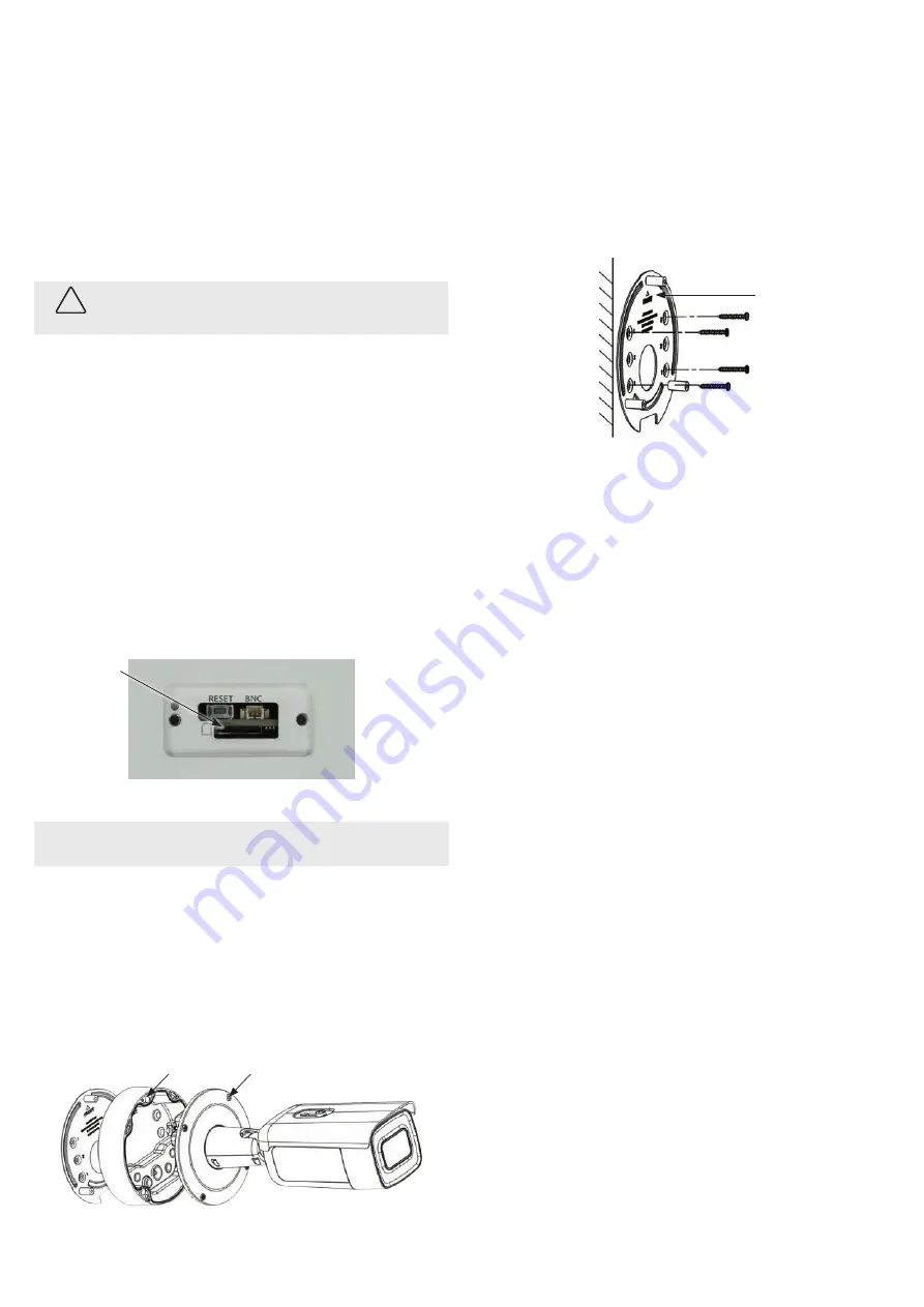
1.
To attach the adapter plate to a mounting surface:
a.
Use the adapter plate as a template to mark the location of the holes for the mounting
screws. Use the four holes marked “1” for the mounting screws. If mounting the camera to
a wall, the “
FRONT
” mark on the adapter plate should point up. If mounting the camera to
a ceiling, the “
FRONT
” mark should point toward the front (lens) of the camera.
“
FRONT
” mark
b.
Drill holes into the surface to accommodate the fasteners for anchoring the camera. If the
interface cables will be routed through the surface, also drill a hole for the cables through
the surface matching the large hole in the adapter plate.
c.
Secure the adapter plate to the surface with four screws. Route the LAN and other
interface cables to the mounting location:
i.
Route the cables through the mounting surface and adapter plate at this time, if
preferred.
ii.
If routing the interface cables through conduit, attached the threaded conduit
adapter to the conduit, and then route the cables through the conduit.
To attach the adapter plate to a gang box:
a.
Anchor the gang box to the mounting surface securely.
The gang box must be able to
support at least four times the weight of the camera.
b.
Remove the cover screws from the gang box. These screws will used to secure the adapter
plate to the box.
c.
If the gang box is on a wall, orient the adapter plate on the gang box so that the “
FRONT
”
mark on the plate is pointing up. If the gang box is on a ceiling, orient the “
FRONT
” mark
on the plate so it points toward the front (lens) of the camera.
d.
Attach the adapter plate to the gang box. For single-gang boxes, use the screws in the
holes marked “
2
”. For double gang boxes, use the screws in holes marked “
1
”.
e.
Route the LAN and other interface cables through the gang box, and then through the
hole in the adapter plate.
f.
For outdoor installations, seal holes drilled through exterior surfaces to block moisture and
other contaminants.
Install the junction box
To install the junction box, first insert the interface cables through the sealing plugs in the junction box,
and then attach the junction box to the adapter plate.
1.
Attach the ground cable to the ground terminal in the junction box.
2.
Remove the largest sealing plug from the junction box. This plug will be used for the LAN cable.
3.
To install the sealing plug on the LAN cable:
a.
Clip the insertion tool provided onto the RG-45 connector of the LAN cable. See
a
below.
b.
Force the insertion tool with the LAN cable through the sealing plug. Observe the
orientation of the sealing plug in the drawing below. See
b
below.
© 2018 Observint Technologies. All rights reserved.


