


4
www.observint.com
© 2017 Observint Technologies. All rights reserved.
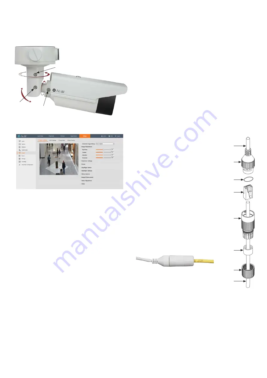
Step 5. Adjust the camera for your surveillance target
1.
While observing live video from your camera in the Live View tab (see above), loosen the Pan,
Tilt and Rotation lock screws at least two turns using the security L-wrench provided, then move
the camera to point at the center of your surveillance target. Tighten the lock screws to hold the
camera in position.
Pan lock screw - Pan: 0˚ ~ 360˚
Tilt lock screw
Tilt: 0˚ ~ 100˚
Rotation lock screw
Rotation: 0˚ ~ 360˚
2.
After adjusting the camera for the preferred field of view, click the
Setup
tab, and then click the
Image
link in the left frame.
Adjust the Brightness Contrast, Saturation and Sharpness of the image as follows.
—
Image Adjustment
submenu (see above): Adjust the Saturation, Hue, Brightness,
Contrast and Sharpness of the video image. Each parameter can be set to a level of
0 ~ 100 either by moving the slider or entering the value in the box on the right. The
effect of the adjustment will appear in the Live View image in the menu.
3.
Open the other submenus on this screen. Adjust the following as needed. Refer to the Camera
Firmware User Manual for your camera for additional information about parameter settings.
—
Exposure Settings
submenu: In this submenu, set the following for the best
performance:
Iris Mode
: Select Auto or Manual. Some cameras may not offer both options.
Exposure Time
: Value ranges from 1/3 to 1/100,000 s. The nominal value is 1/150.
Adjust it according to the lightening condition.
Gain
: Set the gain to show the optimal brightness level.
—
Switch Day and Night
: Select either
Auto-Switch
,
Scheduled-Switch
, or
Triggered by Alarm Input
.
If using
Auto-Switch
, open the
Day/Night Switch
submenu to select the
Sensitivity, Filtering Time, and Smart IR feature ON or OFF.
If using
Scheduled Switch
, set the
Start Time
and
End Time
of the switch, then
open the
Day/Night Switch
submenu to select the
Smart IR
feature ON or OFF.
Also, click the
Common
,
Day
and
Night
tabs to set the Saturation, Hue, Brightness,
Contrast and Sharpness for Day and for Night modes.
—
Day/Night Switch
submenu: You can set the Day/Night switch to Day, Night, Auto, or
Schedule. The option you select determines the submenu options.
Day
or
Night
: These options both have one parameter: Smart IR.
Auto
: If you select Auto switch, you can set the sensitivity (0 .. 7), filtering time and
Smart IR.
Schedule
: Use Schedule to set that
Start Time
and
End Time
for the switch. Smart
IR is also selectable.
—
Backlight Settings
: Backlight settings include BLC Area (Off, Up, Down Left Right
Center), the area to control, and
WDR
(Wide Dynamic Range) ON or OFF.
—
White Balance
: White Balance selection is used to correct colors in the image
depending on the lighting source. You can also set the white balance manually (MWB),
using Automatic White Balance (AWB1), and lock the white balance setting (Locked WB).
—
Image Enhancement
: Options in this submenu include Digital Noise Reduction (DNR)
ON or OFF. If ON, you can also adjust the level of noise reduction.
—
Video Adjustment
: Video Adjustment includes:
Mirror
: Mirror adjustment enables you to flip the image (Up/Down), flip Left/Right
(reflect or Center).
Rotate
: Rotate rotates the image +90 degrees. Rotate and Mirror can be used to
adjust the image in any orientation.
Video Standard
: Select 60 Hz for NTSC format.
Capture Mode
: To make a complete use of the 16:9 aspect ratio, you can enable the
capture mode when you use the camera in a narrow view scene.
—
Other
: Options in this menu depend on the features of the camera.
Using the Waterproof Ethernet Fitting
Install the
Waterproof Ethernet Fitting
on the Ethernet cable end at the camera when moisture
or contamination exists in the area near the camera. The fitting includes several parts that must be
installed in a specific order. To install the fitting:
1.
Place the rubber O-ring over the camera drop cable end cap.
Push the O-ring up to the connector cap.
2.
Place the Lock Nut onto the network cable from the router
or switch as shown in the drawing to the right. The inside
threads must be toward the camera end.
3.
Place the rubber basket onto the network cable above the lock
nut as shown.
4.
Place the end cap onto the network cable above the rubber
gasket as shown. The fingered end must be toward the the
router or switch.
5.
Install an RJ-45 connector onto the network cable.
6.
Plug the RJ-45 connector with the network cable into the
camera network drop cable.
7.
Fit the end cap on the network cable onto the camera drop
cable end cap. Rotate the network cable end cap to lock it in
place.
8.
Push the rubber gasket fully into the end of the network cable
end cap.
9.
Screw the lock nut onto the network cable end cap until it is
fully seated.
Network drop cable
from camera
Network cable from
router or switch
Ethernet Fitting installed
Ethernet Fitting assembled and connected
Drop cable
end cap
Network drop
cable from
camera
Rubber
O-ring
seal
RJ-45
connector
End cap
Rubber
gasket
Network
cable
from
router or
switch
Lock nut


