


2
www.observint.com
•
Ground
: A ground terminal is provided for attaching an earth ground cable to the camera. Follow
local electrical codes for grounding procedures.
NOTE
This camera includes the TVS 2000V lightning protection feature. To use this feature, refer to the
TVS 2000V section at the end of this document for implementation guidelines.
1.
Route a LAN extension cable from a network switch or Network Video Recorder to where the
camera will be installed.
2.
If the camera is not powered using PoE, route 12 Vdc power extension cables from an adequate
power source to the location where the camera will be installed. Voltage input at the camera can be
within the range 12 Vdc ± 25%.
CAUTION
Do not apply power to the camera at this time. Before applying power to the camera, ensure
that the polarity is correct. An incorrect connection may cause a malfunction and can damage
the camera.
3.
Route an earth ground cable to the camera in compliance with local electrical codes.
Step 2. Install the camera
The camera can be mounted on a wall or ceiling, or installed onto an ALI-AF4 junction box.
Installing the camera onto a wall or ceiling
Screws and wall inserts included with the camera are adequate for most surfaces, but more appropriate
fasteners may be needed. The mounting surface should support at least three (3) times the weight of the
camera and mounting bracket assembly.
1.
Determine the best fasteners
for securing the camera
to mounting surface. The
mounting hardware provided
is suitable for most surfaces.
NOTE
: A mounting plate
adapter is provided for
attaching the camera to a
junction box.
2.
Using the Drill Template
provided, mark the location of
the mounting screw holes. If
the drop cable will be routed
through the mounting surface,
mark the location of the hole
for the cable.
NOTE
: The drop
cable can be routed through
the cable channel on the side
of the base.
3.
Drill holes for the mounting
fasteners, and for the drop
cable if needed.
Mounting
screw holes
Wall inserts
Mounting
base
Mounting
screws
Drop
cable
Installing the camera with a junction box
1.
Install the junction box at the installation location.
2.
Route the interface cables into the junction box.
Step 3. Connect the camera to the LAN, ground and power
1.
Attach a ground cable to the camera in accordance with local electrical codes.
2.
Connect the LAN extension cable to the camera network drop cable. If the camera is in an
environment where dust, moisture or other contaminants are present, use the Waterproof Ethernet
Fitting provided to seal this connection. Instructions for using the Waterproof Ethernet Fitting are
provided at the end of this guide.
Camera
Ethernet switch
Network drop cable
from camera
Network cable from
router or switch
Waterproof Ethernet Fitting installed
WARNING
!
Failure of the power or Ethernet connector due to moisture or an other
contaminant is considered an installation error, which voids the warranty. If
installing this camera in a location such as an overhang, shop, garage, kitchen,
etc. where high humidity or dust is present, seal these connections adequately.
3.
If the camera is not powered using PoE, connect the 12 Vdc power cable to the 12 Vdc connector on
the camera drop cable. The polarity of the drop cable connector is shown below.
CAUTION
Before applying power to the camera, ensure that the polarity is correct. An incorrect connection
may cause a malfunction and can damage the camera.
4.
Seal the power cable connectors as needed from moisture and other contamination.
5.
If installing the camera with a junction box:
a.
Detach the dome assembly from the camera base.
b.
Attach the camera base to the junction box. Ensure the seal is properly positioned.
6.
Remove the three lower dome screws, then separate the lower dome from the mounting base. A
security wrench is provided.
7.
Attach the camera mounting base to the mounting location using three screws. DO NOT reattach
the dome assembly to the mounting base at this time.
8.
Power on the camera.
Step 4. Install the Alibi Config Tool software
NOTE:
If the camera LAN extension cable is attached to a Network Video Recorder (NVR), skip this step.
The Alibi Config Tool is a PC-based network utility for discovery of Alibi compatible devices. It provides
an easy way to activate devices, configure camera and recorder network configuration settings, and set
device passwords. It can be installed on a Microsoft® Windows® operating system that has direct access
to the network where your Alibi devices are installed. You can download the Alibi Configuration Tool from
AlibiSecurity.com/Resources
.
1.
Download the Alibi Config Tool from the
AlibiSecurity.com/Resources
website. At the time when
this document was published, the file is named:
alibi-config-tool.zip
and is about 80MB.
2.
Un-zip the file on a computer with Microsoft Windows (Windows 7 or newer) that is connected to
the LAN where your Alibi camera is connected.
3.
Run the file contained in the zip file:
Alibi Config Tool.exe
. Follow the on-screen instructions to
install the file.
4.
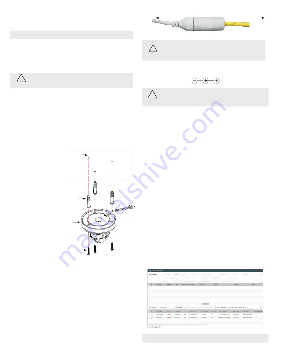
Open the Alibi Config Tool application. When the application opens, it automatically “discovers” and
lists all Alibi compatible devices on the LAN. See below.
NOTE
In the screen above, the tool can discover devices on other sub-nets. It will also list other Alibi compatible
devices on the LAN, and devices with the address 192.168.1.64 (an inactive Alibi device).
© 2019 Observint Technologies. All rights reserved.


