2
www.observint.com
2.
Drill holes for the screws that anchor the base to the ceiling. The mounting hardware provided is
appropriate for most surfaces. However, depending on the surface materials, more appropriate
fasteners may be required.
3.
If using wall inserts for the mounting screws, install them at this time.
4.
Drill a 3/4” hole for the camera drop cable, if necessary. The drop cable can be routed through the
mounting surface, or through a cable channel in the base assembly.
5.
Route video, power and audio extension cables from your power and monitoring equipment to the
mounting location of the camera. Do not apply power to the power extension cable at this time.
6.
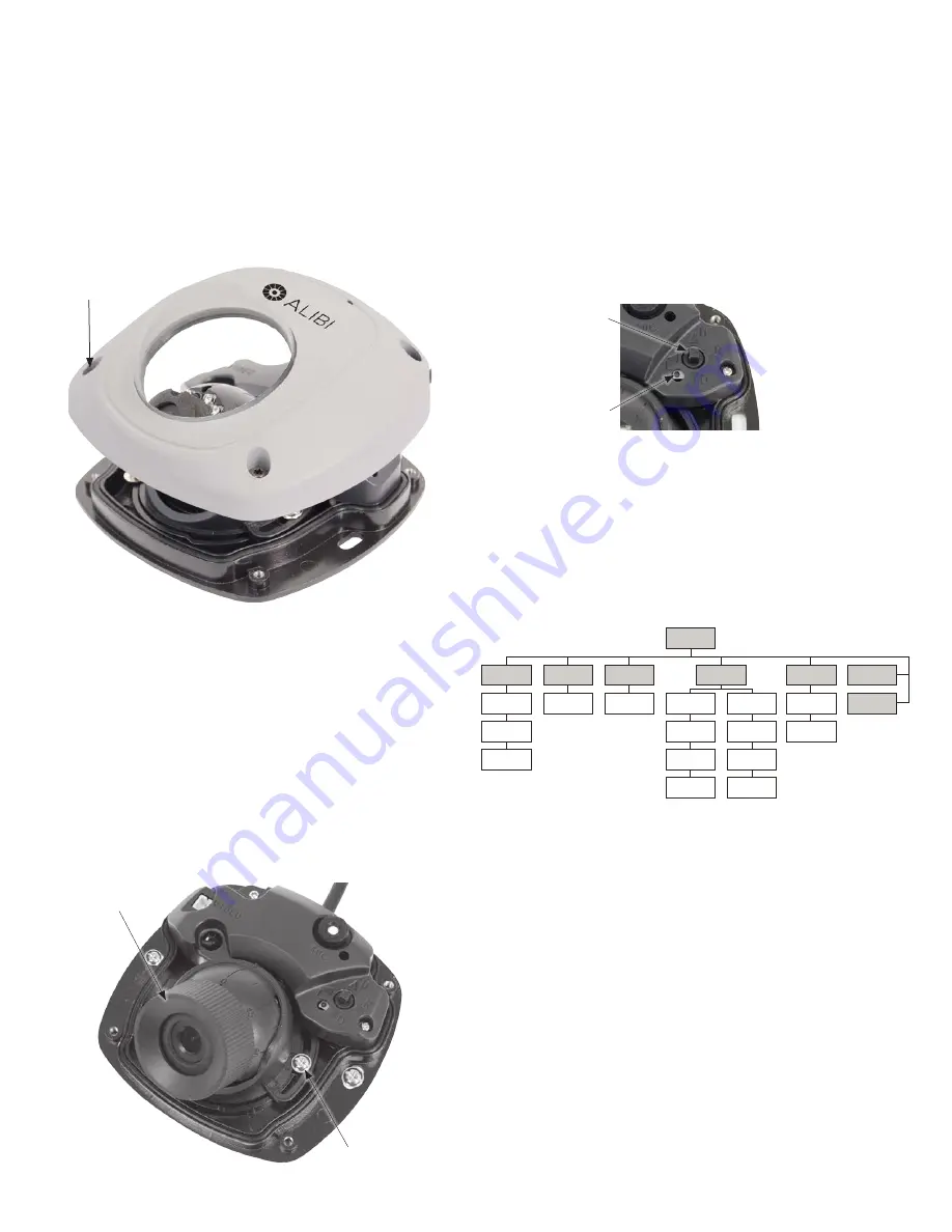
Using the L-wrench provided, loosen the four cover screws, and then lift the cover off of the base
assembly.
Cover (captive)
screw (4)
7.
Connect the camera drop cable to the video, power and audio extension cables.
8.
Place the pad on the mounting location, and then anchor the base assembly to the surface over the
pad.
9.
Connect the video, audio and power extension cables to your monitoring and power equipment.
Apply power to the camera.
10. If you have a CCTV video setup monitor, attach the video lead to the video test cable provided, then
plug the video test cable into the video test jack (see photos above).
11. Verify that you can see a clear video image from the camera on your monitoring equipment, and the
audio is clear.
12. Loosen the pan adjustment screw slightly so that the camera module pan (left and right) can be
adjusted.
13. Attach the “adjustor” tool provided to the camera module. See below.
Adjustor tool
Pan lock screw
14. While holding the adjustor in place and observing the video from your camera, adjust the pan, tilt
and rotation of the camera module to aim it at your surveillance target.
CAUTION
: Avoid touching the camera lens.
15. Remove the adjustor tool.
16. Tighten the pan lock screw.
17. Use the OSD menu system to customize the settings for your camera. See
OSD Menu System
below.
18. Reinstall the camera cover.
OSD Menu System
1.
Locate the OSD joystick on base assembly.
Joystick
Reset button
The OSD joystick is used to open the OSD menu and navigate through the menus. To open the
camera menus and select a menu option, press the joystick down (in toward the base assembly).
To navigate the menus, rock the joystick up (
p
, U) or down (
q
, D) to move through the parameter
list menus vertically, rock the joystick left (
t
, L) or right (
u
, R) to change the parameter value
that appears for the parameter. Press the joystick down (in toward the base assembly) to select the
parameter value shown. Changes made to the OSD setup must be saved to be retained. See NOTES
below.
2.
Open the OSD menus by pressing the joystick in toward the base assembly. The OSD menu tree is
shown below.
SETUP
NR
Brightness
Mirror
Contrast
Language
Color Gain
System Setup
Sharpness
Motion
Alarm
Function
Setup
Save & Exit
Reset
Lens Type
AGC
DWDR
Exposure
Mode
WB
Mode
D&N
Video Setup
3.
Navigate through the menu OSD menus as adjust the camera function as needed.
Notes on the OSD
:
After making changes to the parameters in the OSD menu, they must be SAVED to retain them after closing
the menu. See the SAVE & EXIT submenu below.
•
EXPOSURE submenu
:
—
Lens: Select FIX or IRIS
—
AGC: Select HIGH, MIDDLE, LOW or OFF for the best performance.
—
DWDR: Select HIGH, MIDDLE, LOW or OFF for the best dynamic range performance.
•
WB (White Balance) submenu
:
—
Mode: Use AUTO 1 for environments where the color temperature is stable. Use AUTO 2 for
environments where the color temperature changes.
•
DAY & NIGHT submenu
:
—
Mode: Select SMART, AUTIO, B/W, or COLOR. If SMART is selected, day and night mode switches
automatically.
—
SET: Select ON (IR LED is on), or OFF.
© 2014 Observint Technologies. All rights reserved.


