7
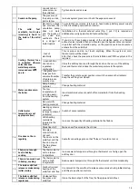
The back of the boiler and connections are shown in Fig. 4 where:
Figure 1
- Item 1 is an R1" connection with an outer thread for the flow pipe,
- Item 2 is an R 1" connection with an outer thread for the return pipe,
- Item 3 is an R1/2" connection with an inner thread for installation of the thermal valve safety pipe,
- Item 4 is an R1/2" connection with an inner thread for safety valve installation.
7.1.
FLOW PIPE AND RETURN PIPE (Fig. 4, Items 1 and 2 and Fig. 7 and 8, Items 3
and 10)
The size of the flow pipe and return pipe outlets is 1" and may not be reduced or tapered before the first branch. Use 1"
steel pipe or copper pipe of outer diameter Ø 28 mm (or larger diameter).
While installing the system, absolutely make sure that pipe slopes are 0.5% (5 mm of pipe length) and that the air is
released from the system (from the boiler, pipes, radiators).
You can install a combination temperature and pressure gauge on the flow pipe, although both thermometer and pressure
gauge are installed at the front of the stove.
On the return pipe, install a by-pass line with a pump, expansion vessel and a spigot for filling up and emptying the
system. When you install the pump, take note of the pump’s direction.
Note:
Only install the by-pass line if there are conditions for gravity heating.
7.2.
THERMAL VALVE WITH BUILT-IN THERMAL PROTECTION AND ADDITIONAL
ELEMENTS FOR CONNECTION
To install thermal valve it is necessary to purchase and install:
1. Thermal valve with built-in thermal protection type 544, 1/2", product Caleffi (Fig. 7a) and Fig. 7, Item 13.
2. Slope pressure regulator with manometer 1/2", the same or similar as shown in Fig. 7b and Fig. 7, Item 19.
3. Filter for cold water at the input of the water supply to the thermal valve, Fig. 7, Item 20
4. Filter for hot - boiling water intake of the boiler and water outlet of thermal valve, Fig. 7, Item 21.
Note:
These components are not included with product for central heating you bought!
Installation of thermal valve with built-in thermal protection (Fig. 7, Item 13 and Fig. 7a) with additional elements ensuring
safe operation, such as pressure regulator (Fig. 7, Item 19 and Fig. 7b). Water filter on the boiler intake (Fig. 7, item 20) and
water filter on the boiler outlet in closed central heating system is MANDATORY. This specially refers to a closed system,
when the radiators are submerged and where in case of termination of the pump operation for any reason, the water
temperature in the boiler rapidly increases and overheating occurs very quickly.
In the open central heating system, installation of thermal fuse is not mandatory.
7.2.1.
THERMAL VALVE WITH BUILT-IN THERMAL PROTECTION (Fig. 7, Item 13 and Fig. 7a)
Thermal fuse is installed near the stove, depending on the available space. It can be installed in any position. You should
take into account the direction of cold water intake and hot water outlet from the boiler which is clearly marked on the valve
body.
The thermal fuse probe (Fig. 7, Item 22) is best to place in the thermal valve connection (Fig. 7, Item 18). It can be placed
on the discharge - distribution pipe (Fig. 7, Item 3) but at a distance from the boiler of 500 mm the most or at the highest point
of the boiler before the exhaust pipes.
Seal it with hemp or other sealing material by tightening.
Fig. 7 shows the thermal valve installation diagram.


