7
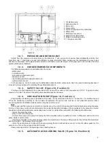
Figure 18
10.1.
PRESSURE AND RETURN LINE
Outlets from the pressure and return lines on the boiler are 1’’ and you must not narrow them additionally until the first
branching. Use 1’’ steel tube or copper tube Ø28mm (or larger diameter). When carrying out the installation, be sure to pay
attention to the slopes of the pipes, which should be 0.5% (5mm per meter length of the pipe) and to the air-bleed from the
system (boiler, pipes, radiators).
10.2.
COOKER EMBEDDED COMPONENTS
The following components are embedded into the cooker:
- safety valve,
- circulation pump,
- automatic air-bleed valve (pot),
- expansion vessel,
- tap for filling and discharging the lines, and
- water pressure sensor.
For those reasons, it is not necessary to additionally embed the listed components, which is a great advantage because it
reduces the time and space for installing the specified components
.
10.3.
SAFETY VALVE (Figure 18, Position 6)
It is placed on the backside of the cooker behind the frame of the cooktop. Inlet connection is of R1/2’’. It opens at water
pressure of 2.5 bar. The outlet of the safety valve should be piped to the sewer.
10.4.
CIRCULATION PUMP (Figure 18, Position 1)
A high-quality circulation pump is installed on the cooker, on the return line with the R1’’ connection. It is switched on and
off by the electronics according to the set water temperature. The pump axis must be in the horizontal position. When
connecting with the installation, make sure the pump does not turn over!
Note:
If the cooker and the pump do not work for a long time (e.g. for a month), the pump shaft may be blocked, causing the pump
to stop. In this case, you should not commission the cooker, because the blockage of the pump leads to the cessation of water
circulation in the heating and water overheating lines. In order to unblock the pump shaft, the following should be done:
- remove the protective grille,
- place a cloth under the pump,
- unscrew the screw on the pump front using the flat screwdriver with a tip width of 5-7mm. A little water will run from the
pump, which is quite normal,
- insert the screwdriver in the pump opening, place the screwdriver in the pump shaft groove and by turning the screwdriver
and the shaft left – right release the pump shaft,
- return the pump screw to its place in the pump opening, fasten it well and take care not to drop the rubber gasket on the
pump screw. Turn on the pump and check if it works.
Check pump operation at the beginning of each heating season.
10.5.
AUTOMATIC AIR-BLEEDING VALVE (Figure 18, Position 8)
1.
Circulation pump
2.
Expansion vessel
3.
Return line
4.
Pressure line
5.
Pipe for supplying air for combustion
6.
Safety valve
7.
Water pressure sensor
8.
Automatic air-bleed valve
9.
Filling and discharging tap
10.
Flue pipe connection

