


7 ATEX specific conditions for safe use
It is important that the drive unit is dismounted before removing the impeller.
The maintenance interval for the mixer depends on the application - shorter or longer service interval may appear.
Handle the mixer with care and follow the recommended inspection to prevent unnecessary damage.
Make sure to follow section 5.2 Inspection and below as additional maintenance for ATEX options.
7.7
Additional maintenance for ATEX
Inspect/clean/lubricate
Weekly/
Supplier instruction
after each 100 hours of operating
Drive rotor
Before each mounting of drive
unit: Check total run-out before every
mounting
Gear
x
Clean vent screw
x
Check for oil leakage
x
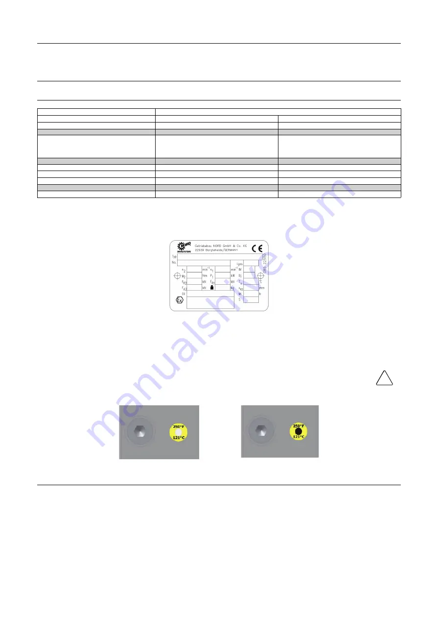
Check temperature sticker
x
Motor
x
Clean surface to avoid overheating
x
NOTE
Please pay special attention to the stated maintenance interval (MI) of the gearbox. The gear can have a shorter lifetime
than the mixer.
NOTE
Beware of the color change in the temperature sticker on the gear box.
If the surface temperature gets too high, the sticker will change color to black in the middle.
Stop the gear immediately if the sticker is black in the middle.
CAUTION
The mixer must NOT resume operation before cause of overheating has been investigated and found.
!
4307-0103
41
Содержание LeviMag
Страница 2: ......
Страница 52: ...10 Parts lists Service kits Product overview WP50 10 1 Product overview WP50 4307 0055 52...
Страница 54: ...10 Parts lists Service kits Product overview WP81 10 2 Product overview WP81 4307 0056 54...
Страница 56: ...10 Parts lists Service kits Drive unit WP50 10 3 Drive unit WP50 4307 0057 56...
Страница 58: ...10 Parts lists Service kits Drive unit WP81 10 4 Drive unit WP81 4307 0058 58...
Страница 60: ...10 Parts lists Service kits Speed Sensor variants 10 5 Speed Sensor variants 4307 0117 60...
Страница 62: ...10 Parts lists Service kits Tools 10 6 Tools 4307 0059 62...
Страница 64: ...10 Parts lists Service kits Tools 4307 0060 64...
Страница 67: ...67...