Specifications
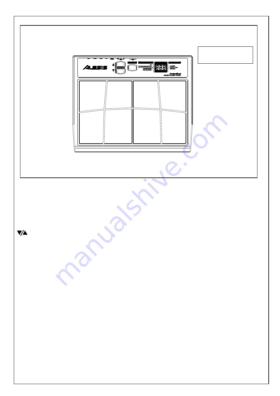
8 PLAYING PADS
These are the eight playable velocity sensitive pads.
FUNCTION BUTTON
This button is used to select different operation
BUTTONS
These two buttons are used to cycle through presets, as well as increase and
decrease values when a parameter is selected.
LED SCREEN
The LED screen displays information about the state of the ControlPad including
kit number and function parameters. The screen also features a small “Activity”
LED which will light up each time that a pad, trigger, or pedal is engaged.
FUNCTION LEDs
Each function in Edit Mode is paired with a corresponding LED on the panel.
When in Edit Mode, these LEDs will reflect which function is currently being
edited.
2 EXTERNAL TRIGGER INPUTS
These two ¼” inputs can be used for connecting external triggers, pads, and pedals.
Alesis offers a pad expansion kit, as well as a cymbal expansion kit sold separately.
2 SINGLE FOOTSWITCH INPUTS
These two ¼” inputs are used for connecting external footswitches to function as a
high hat pedal or bass drum pedal.
DUAL FOOTSWITCH INPUT
This is a ¼” TRS input which can be used with a dual pedal footswitch for
selecting kits and incrementing or decrementing values on the ControlPad.
SERVICE MANUAL
MODEL:
CONTROL PAD
Содержание ControlPad
Страница 8: ...3 DISASSEMBLE THE MAIN PCB ASS Y Fig3 A REMOVE 5 1 4 JACK NUTS B REMOVE 3 SCREWS Fig 3...
Страница 9: ......
Страница 10: ......
Страница 11: ......
Страница 12: ...Confidential Alesis Service Manual 8 31 0175 B ALESIS ControlPad LDS1 SCHEMATIC AND PCB FILES...
Страница 13: ......
Страница 14: ......
Страница 15: ......
Страница 16: ......
Страница 17: ......
Страница 18: ......
Страница 19: ......
Страница 20: ......
Страница 21: ......
Страница 22: ......
Страница 23: ......
Страница 24: ......
Страница 25: ......
Страница 26: ......
Страница 27: ......
Страница 28: ......
Страница 29: ...Confidential Alesis Service Manual 8 31 0175 B ALESIS ControlPad LDS1 BOM...


