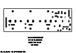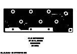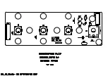
②
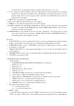
THD+N: 1%±0.01( when THD @1% output power over36mW)
③
RESIDUAL NOISE: 0.2mv±0.1mv
(
set to MUTE, FILTERFREQ
:
20KHz)
④
Output Frequency Respond: 300HZ~14KHZ/-3dB
⑤
Plug/unplug “HEADPHONS” no pop noise.
AMP board
note: if no special require, all testing under below condition.
A: from “AUX INPUT” RCA input signal.
B: from “SPEAKER OUT” jack output signal, load 8ohm/100w resistor.
1.
“FOOT SWITCH” jack testing:
plug in standard footswitch to “up” and “down”, verify if can function as the Program Up and Program
Down buttons.
2.
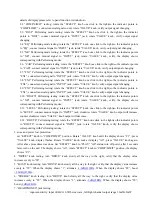
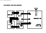
“EXPRESSION INPUT” jack: Connects to a B50K potentiometer(details connection please refer to the
illustration.), set to “LEVEL” Performing mode “Pd” status. Connect musical signal to “INPUT” jack,
connect headphone to “HEADPHONES”, when clockwise rotate potentiometer to maximum, measure
potentiometer pin 1.2.3, the DC voltage should be: 1.65V, 2.04V, 2.0V, as well the volume increase; when
counterclockwise rotate potentiometer to minimum, measure potentiometer pin 1.2.3, the DC voltage should
be:1.65V, 1.65V, 2V, as well volume decrease.
3.
“STERO LINK OUTPUT” jack testing.
Condition:
connect signal to “INPUT” jack(series connect one 470Kohm resistor)
①
②
between ground and signal output parallel connect one 32ohm/1w resistor.
③
input sensitivity: input 1KHZ/-16.5dB sine wave, left/right channel output rang 36mW±2mW.
④
THD+N: 1%±0.01(distortion at 1%, output over 36mW)
⑤
Frequency response: 300Hz~14KHz/-3Db
⑥
Plug/unplug “HEADPHONS” no pop noise.
4.
“SPEAKER OUT” jack testing:
Requirement: details criterion please refer to appendix. When the “SPEAKER OUT” is plugged the speaker
will mute.
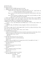
SOFTWARE TESTING
Requirement:
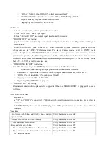
a: "UP" and “DOWN” connect to 1/4”CK plug with normally-open switch.(connection please refer to
illustrator)
b: "EXPESSION" jack connect to 1/4”CK plug with B50K potentiometer. .(connection please refer to
illustrator)
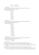
Procedures
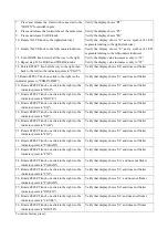
1. Hold down both buttons and VALUE knob, and turn
on power switch.
Verify the display shows “dd”
2. Release both buttons and VALUE knob.
Verify the display shows “ES”
3. Press and release down button
Verify the display shows “PL”
4.Press and release up button
5.
Press and release both buttons at the same time
6.
Press and release the footswitch connected to the
“UP” footswitch inputs
Verify the display shows “Pr”
Verify the display shows “Pb”
Verify the display shows “Pr”
Содержание BASSFIRE 60
Страница 5: ......
Страница 6: ...Confidential Alesis Service Manual 8 31 0159 A ALESIS BassFire 60 GB0 Test Procedures...
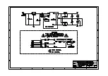
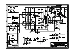
Страница 17: ...Confidential Alesis Service Manual 8 31 0159 A ALESIS BassFire 60 GB0 SCHEMATIC AND PCB FILES...
Страница 18: ...GAX_MAIN_V1 1 sch 1 Mon Feb 28 16 17 24 2005...
Страница 19: ...GAX_MAIN_V1 1 sch 2 Mon Feb 28 16 17 26 2005...
Страница 20: ......
Страница 21: ......
Страница 22: ...sch 1 Mon Feb 28 16 08 43 2005...
Страница 23: ...sch 1 Mon Feb 28 16 07 56 2005...
Страница 24: ......
Страница 25: ......
Страница 26: ......
Страница 27: ......
Страница 28: ......
Страница 29: ......
Страница 30: ......
Страница 31: ......
Страница 32: ......
Страница 33: ......
Страница 34: ......
Страница 35: ......
Страница 36: ......
Страница 37: ......
Страница 38: ......
Страница 39: ...Confidential Alesis Service Manual 8 31 0159 A ALESIS BassFire 60 GB0 BOM...


