


aleo solar GmbH
| Marius-Eriksen-Straße 1 | 17291 Prenzlau | Germany |
Installation manual Ver. 4.8, 05/2021, en
Page 12 of 20
10 Details of mechanical mounting
10.1 Aligning the mounting profiles
10.1.1 Permissible alignment
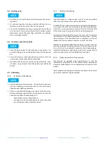
Fig. 3
Permissible alignment of mounting profiles
a, b
: Parallel profiles for mounting
10.1.2 Not permissible alignment
Fig. 4
Not permissible alignment of mounting profiles
a
: Profiles not parallel to each other
b
: Profile neither parallel nor perpendicular to the module edges
10.2 Clamp mounting for modules with standard frame
10.2.1 Arranging the clamps
Permissible clamp arrangement
Fig. 5
Permissible clamp arrangement
a
: Symmetrical clamping on long sides
b
: Symmetrical clamping on the short sides
Not permissible clamp arrangement
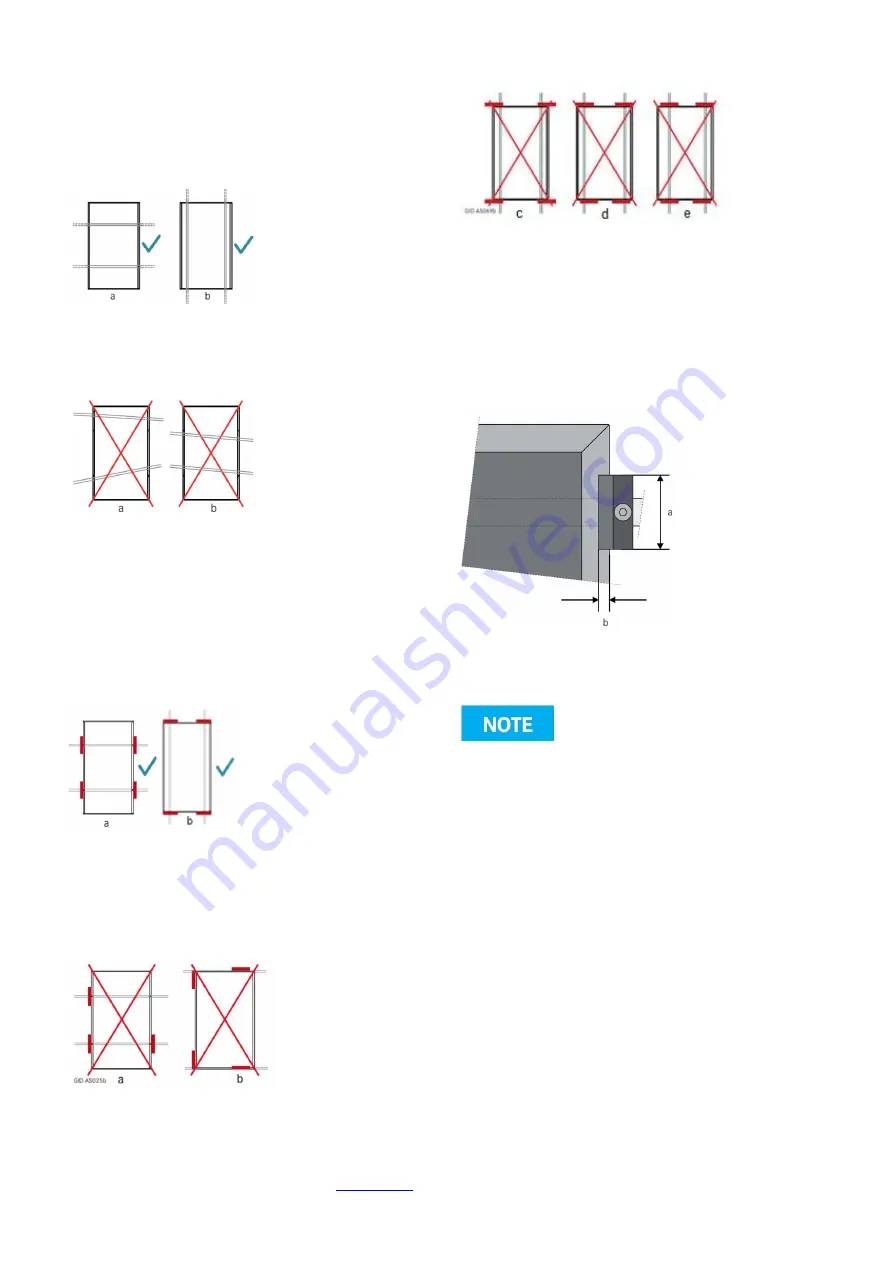
Fig. 6
Not permissible clamp arrangement (1)
a
: Missing clamps
b
: Clamping on both short and long sides
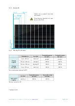
Fig. 7
Not permissible clamp arrangement (2)
c
: Protruding clamps
d
: Opposing clamps have different distances to the module corners
e
: Asymmetrical clamps on the short side
10.2.2 Clamp dimensions
Observe the following information for clamp lengths and depths.
Clamp lengths and depths
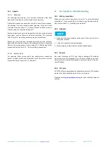
Fig. 8
Definition of clamp length and depth for framed modules
a
: Clamp length
b
: Clamp depth
The required minimum length of a clamp (parallel to the frame
side) is 30 mm.
The required minimum depth of a clamp (perpendicular to the
frame side) is 3 mm.
aleo solar recommends a clamp depth of 5 mm.
Depending on the ambient conditions (e.g. angle, suction load
or tolerances of the substructure) a higher minimum area per
clamp may be required.
Observe the instructions of the clamp manufacturer.
10.2.3 Tightening torque for clamp mounting
Tighten the screws on the clamp manually. If you use an automatic
screwdriver, then set a suitable maximum tightening torque. You
can find details for this in the manufacturer’s documentation for
the substructure.


