aldes EVEREST XV Скачать руководство пользователя страница 14

14

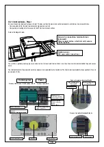
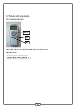
2.8.2 Connecting electrical cables - power or control

Unscrew the cross-head screws on the access hatch to the terminal block. Pass the power supply cables through the cable glands to ensure air 
tightness.  

Cable gland for 
control system cable

The power supply cable rigid conductors or with end pieces are directly connected to the spring terminals (no tools required).  It is possible to release 
the conductors using a screwdriver to actuate the orange latch in front of the conductor insertion hole. 
The flexible conductors without end pieces must be inserted by actuating the latch to release the spring (see photo below). 
By applying a light effort on the latch, you can verify that the conductor is correctly inserted if the latch recedes 1 mm without resistance. 
The bridges slot into the purpose-built holes in the terminal (see photo below). 

Connecting a conductor to a terminal

Connecting a bridge to a terminal (for inlet/outlet dampers)

3-terminal bridge

2-terminal bridge

Cable gland for 
power cable

Содержание EVEREST XV

Страница 1: ...Download the settings guide from our website or directly from the SD card provided www aldes com EVEREST XV Installation instructions EN...

Страница 2: ...Connecting the CO2 sensor 9 2 6 5 Optional internal water coil 10 2 6 6 Constant pressure option 10 2 6 7 LON option 11 2 7 Hydraulic connection 11 2 7 1 Connecting condensate drains general 11 2 7 2...

Страница 3: ...1 3 2 Dimensions of external accessories 22 3 2 1 Flexible sleeves 22 3 3 Adapter piece drawings 23 3 4 Diameters of internal water coil collectors 24 4 CONTROL OPTIONS 25 4 1 Hard wired control optio...

Страница 4: ...l power supply to the device must be disconnected prior to any maintenance or cleaning operation Ensure that the unit may not be turned on accidentally If a power cable is damaged it must be replaced...

Страница 5: ...ack of the quick access hatch and another is on the side panel The unit is packaged in plastic film protected with cardboard corner pieces All accessories ordered with the unit are delivered unassembl...

Страница 6: ...of the slings around the handling bars and place the spacers above the unit to prevent damage to the structure See diagram below Spacers Slings Handling bars 2 3 Parts supplied in packaging 2 3 1 Doc...

Страница 7: ...e able to open to a minimum of 90 to enable replacement of the filters The central black door must open to an angle of 180 to enable access to switches and the control system NB The electrical box has...

Страница 8: ...ce with applicable standards and regulations 2 6 2 Fitting an insulation damper on fresh air discharged air duct Dampers are supplied with pre wired servo motors an RG link cable whether one or two da...

Страница 9: ...block according to the diagram below 24 V AC GND and 1 10V input 3 way connector 3 way connector Damper servo motor cable RG cable To damper To terminal block 3 way connector 3 way connector Damper se...

Страница 10: ...t be watertight We recommend that you protect the connections between the servo motor cable and the BW cable using at least an IPX5 protection Attach the temperature sensor to the 3 way valve of the i...

Страница 11: ...ory pre wired and connected to the connection terminal block Connect the RJ12 cable labelled R11 waiting on the spar to one of the two female RJ12 connectors on the LON module The LonWorks networks ca...

Страница 12: ...e air circuit on a coil con taining at least two rows We recommend that you hold the collector with a clamp while connecting it to prevent damage to the collector that could cause leaks Ensure the joi...

Страница 13: ...the transformer The transformer is protected by fuses upstream 1 A and downstream 2 5 A Access to connection terminal block screwed Power supply mains electrical coil sensor control options Quick acce...

Страница 14: ...nductors using a screwdriver to actuate the orange latch in front of the conductor insertion hole The flexible conductors without end pieces must be inserted by actuating the latch to release the spri...

Страница 15: ...the frost protection coil or heating coil optional We recommend a circuit breaker with a 20 A rating and a 300 mA differential sensitivity along with a cable cross section of 2 5 mm Electric coil pow...

Страница 16: ...Pa F7 HE filters 250 Pa ECO max 450 Pa Consult the configuration notice to reset the pressure loss when changing the filters under a dynamic alarm 2 10 Configuring the TCP IP protocol Connect the RJ45...

Страница 17: ...IP address and DNS server address Two paths are possible depending on the version of Windows a with Windows XP Start Connections Display all connections right click local area connection Properties I...

Страница 18: ...18 b with Windows 7 Configuration panel Network and Internet Network and Sharing Centre Local network connection Properties Click IP v 4 Properties...

Страница 19: ...the PCB 255 255 255 0 identical to PCB 3 Open a web page using Internet Explorer and enter the IP address of the PCB The next page is displayed Enter the user name and password depending on your profi...

Страница 20: ...p ESC Rotate the wheel to browse a menu Press the wheel to select a menu Press ESC to quit a menu 2 11 2 Menu access To access the User level no password is required To access the Installer level ente...

Страница 21: ...P7 P8 P9 P10 P11 P12 P13 P14 P15 600 1200 940 569 190 134 389 435 35 352 250 121 252 60 201 157 40 556 50 1200 1200 940 840 190 134 638 685 35 412 315 121 252 50 252 323 556 50 1600 1200 1170 907 240...

Страница 22: ...mm B mm C mm D std duct mm D1 int mm E mm F mm G mm T1 600 190 435 465 220 300 250 251 30 110 117 50 1 bed 1200 190 685 715 220 300 315 316 30 140 180 2 bed 1600 240 765 785 260 300 350 351 30 155 225...

Страница 23: ...C Dimension D Dimension E Dimension F Dimension G Dimension H Dimension I Dimension J Size 1 435 190 250 139 399 469 153 224 156 Size 2 685 190 315 207 649 719 153 224 192 Size 3 765 240 355 202 729...

Страница 24: ...he coils admit a maximum pressure of 8 bar Water coils 3 way valve female connection Models Coil type Copper collector Ext Gas inches Valve flow factor Kvs DN mm XV 600 1 row 1 2 1 6 15 XV 1200 1 row...

Страница 25: ...triggers forced ventilation at a given speed to be configured in software Connect M8 M7 for the fire alarm Caution according to article CH38 ErP for public buildings and containing several units that...

Страница 26: ...st temperature 1 100 C 3x0022 Ambient temperature 1 100 C 3x0025 Air supply temperature 1 100 C 3x0020 Pressure on exhaust filter Pa 3x0032 Max alarm threshold on exhaust filter Pa 3x0040 Pressure in...

Страница 27: ...27 NOTES...

Страница 28: ...www aldes com 11078801 09 2015 RCS 956 506 828 Printed in France...

Отзывы: