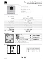
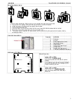


ALD-5404
Specification & Installation manual
3
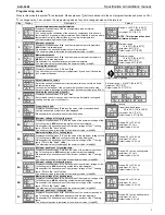
Programming mode
When in this mode this symbol
is displayed. Please press on button to advance to the next program function and press on
∆
or
∇
to change value. You can leave the programming mode at any time, changed values will be recorded.
Step Display
Description
Values
1
Internal temperature sensor Calibration:
Display switches between “
tS1
” and temperature read by internal
temperature sensor.
You can adjust the calibration of the sensor by comparison with a known
thermometer. For example if thermostat has been installed in an area where
temperature is slightly different than the room typical temperature
(thermostat place right under the air diffuser).
Range : 5 to 45ºC [41 to 99ºF]
(max. offset ± 5ºC)
Increment: 0.1ºC [0.2ºF]
NOTE: This thermostat has been
calibrated at factory
2
Minimum set point:
Display switches between “
Stp
” and the minimum set point temperature.
MIN
symbol is also displayed.
Please select the desired minimum set point temperature.
The minimum value is restricted by the maximum value. (step #3)
Minimum range
10 to 35ºC [50 to 95ºF]
Increment: 0.5ºC [1ºF]
Default value: 15ºC [59ºF]
3
Maximum set point
Display switches between “
Stp
” and the maximum set point temperature.
MAX
symbol is also displayed.
Please select the desired maximum set point temperature.
The maximum value is restricted by the minimum value. (step #2)
Maximum range
10 to 35ºC [50 to 95ºF]
Increment: 0.5ºC [1ºF]
Default value: 30ºC [86ºF]
4
Locking the set point :
Display switches between “
LO
C
” and “
Stp
”.
You can lock or unlock the set point adjustment by end user. If locked the
lock symbol will appear.
Default value: Unlocked
5
Adjust internal set point:
Select the desired locked set point temperature; this one should be within
the temperature range.
Lock symbol will appear if the set point was locked at the previous step.
Set point value is restricted by the minimum & maximum value.(step #2 & 3)
Set point range : 10 to 35ºC [50 to 95ºF]
Increment: 0.5ºC [1ºF]
Default value: 22.0ºC [72ºF]
6
Locking the control mode (cont’d):
Display switches between “
Ct
L
” and “
Aut
”.
Select which control mode you want to authorize: Automatic cooling and
heating, heating only or cooling only.
Default value: Cooling
7
Proportional band:
Display switches between “
Pbd
” and the value of the proportional band.
Cooling and heating symbols are also displayed.
Please select the desired value of proportional band.
Proportional band range :
0.5 to 5.0ºC [1.0 to 10.0ºF]
Increment: 0.5ºC [1.0ºF]
Default value: 2.0ºC [4.0ºF]
8A
Minimum voltage of 1st cooling ramp:
Display switches between “
CL
” and the value of the minimum voltage of the
1st cooling ramp.
MIN
and cooling symbols are also displayed.
Please select the desired value of the minimum voltage of the 1
st
cooling
ramp.
(This is the “zero” value)
The minimum value is restricted by the maximum value. (step #8B)
Range: 0.0 to 10.0 Volt.
Increment: 0.1 Volt.
Default value: 0.0 Volt
8B
Maximum voltage of 1st cooling ramp:
Display switches between “
CL
” and the value of the maximum voltage of the
1st cooling ramp.
MAX
and cooling symbols are also displayed.
Please select the desired value of the maximum voltage of the 1
st
cooling
ramp.
(This is the “span” value)
The maximum value is restricted by the minimum value. (step #8A)
Range: 0.0 to 10.0 Volt.
Increment: 0.1 Volt.
Default value: 10.0 Volt
8C
Minimum position of 1st cooling ramp:
Display switches between “
CLd
” and the value of the minimum position of
the 1st cooling ramp.
MIN
and cooling symbols are also displayed.
Please select the desired value of the minimum position of the 1
st
cooling
ramp.
The minimum position is restricted by the maximum value. (step #8B)
Range: 0.0 to max. cooling ramp.
Increment: 0.1 Volt.
Default value: 0.0 Volt
9A
Minimum voltage of 1st heating ramp:
Display switches between “
Ht
” and the value of the minimum voltage of the
1st heating ramp.
MIN
and heating symbols are also displayed.
Please select the desired value of the minimum voltage of the 1
st
heating
ramp.
(This is the “zero” value)
The minimum value is restricted by the maximum value. (step #9B)
Range: 0.0 to 10.0 Volt.
Increment: 0.1 Volt.
Default value: 0.0 Volt
9B
Maximum voltage of 1st heating ramp:
Display switches between “
Ht
” and the value of the maximum voltage of the
1st heating ramp.
MAX
and heating symbols are also displayed.
Please select the desired value of the maximum voltage of the 1
st
heating
ramp.
(This is the “span” value)
The maximum value is restricted by the minimum value. (step #9A)
Range: 0.0 to 10.0 Volt.
Increment: 0.1 Volt.
Default value: 10.0 Volt
9C
Minimum position of 1st heating ramp:
Display switches between “
Htd
” and the value of the minimum position of
the 1st heating ramp.
MIN
and heating symbols are also displayed.
Please select the desired value of the minimum position of the 1
st
heating
ramp.
The minimum position is restricted by the maximum value. (step #9B)
Range: 0.0 to max. heating ramp.
Increment: 0.1 Volt.
Default value: 0.0 Volt