


9 — Connecting to external alarm equipment
9-2
2902 MainStreet Technical Practices
90-2906-01 May
2002
9.1
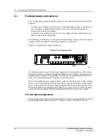
External alarm connections
The external alarm connector allows connection to other devices for the following
purposes:
•
to monitor an external circuit or piece of equipment that is part of your network
(for example, an uninterruptible power source) by detecting the opening or
closing of the Alarm In contacts
•
to activate an external alarm device, such as a light or buzzer, using the Event
Status or the System Status relay
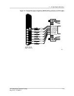
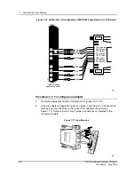
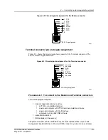
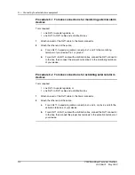
If connecting permanently to a rack-mount slide assembly, create a service loop long
enough to allow the drawer to be fully opened (see section 4.3).
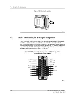
Figure 9-1 identifies the Alarm connector.
Figure 9-1 Alarm connector
The Alarm In pins connect to the relay contacts of the external device. The state of
the Alarm In pins is configured through an NMTI session to detect normally open or
normally closed contacts. The opening or closing of the Alarm In pins causes the
alarm “External Alarm Raised” to appear in an alarm queue.
The Event and Status relay contacts (pins) connect to the drive lines on the external
devices. The Event Status and the System Status relays activate the external alarm
devices. When there are unacknowledged alarms in the major alarm queue, the Event
Status LED illuminates and the Event Status relay closes. When a system problem
occurs, the System Status LED illuminates and the System Status relay closes.
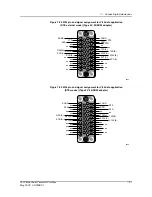
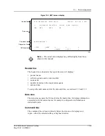
Pin and signal assignments
The external alarm connector (labeled Alarm), is an RJ11 connector with the pin and
signal assignments shown in Figure 9-2. Figure 9-3 shows the alarm circuit.
10434
Line-1
Slot 2
Slot 1
Line-2
Modem
Terminal
Rx-1
Tx-1
Rx-2
Tx-2
Alarm
Alarm
Loop
Display
Status
2
1
U
O
I
P1
P2
EDG Sig/Gnd
Содержание MainStreet 2902
Страница 1: ...2902 MainStreet Network Termination Unit Release 1 0 H T E C H N I C A L P R A C T I C E S ...
Страница 40: ...3 Mounting the unit 3 8 2902 MainStreet Technical Practices 90 2906 01 May 2002 ...
Страница 50: ...4 Ground and power connections 4 10 2902 MainStreet Technical Practices 90 2906 01 May 2002 ...
Страница 68: ...6 Connecting to the network 6 4 2902 MainStreet Technical Practices 90 2906 01 May 2002 ...
Страница 90: ...7 Connecting to data devices 7 22 2902 MainStreet Technical Practices 90 2906 01 May 2002 ...
Страница 108: ...10 Node management 10 10 2902 MainStreet Technical Practices 90 2906 01 May 2002 ...
Страница 150: ...14 CPSS 14 6 2902 MainStreet Technical Practices 90 2906 01 May 2002 ...
Страница 168: ...16 E1 circuit operating parameters 16 4 2902 MainStreet Technical Practices 90 2906 01 May 2002 ...
Страница 218: ...20 Codirectional DCM 20 6 2902 MainStreet Technical Practices 90 2906 01 May 2002 ...
Страница 234: ...22 HCM rate adaption 22 10 2902 MainStreet Technical Practices 90 2906 01 May 2002 ...
Страница 246: ...23 Cross connecting circuits 23 12 2902 MainStreet Technical Practices 90 2906 01 May 2002 ...
Страница 254: ...24 Visual indicators 24 8 2902 MainStreet Technical Practices 90 2906 01 May 2002 ...
Страница 266: ...25 Alarms 25 12 2902 MainStreet Technical Practices 90 2906 01 May 2002 ...
Страница 278: ...26 System diagnostics 26 12 2902 MainStreet Technical Practices 90 2906 01 May 2002 ...
Страница 298: ...27 Loopbacks 27 20 2902 MainStreet Technical Practices 90 2906 01 May 2002 ...
Страница 332: ...Glossary GL 8 2902 MainStreet Technical Practices 90 2906 01 May 2002 ...
Страница 343: ......
Страница 344: ... 2002 Alcatel All rights reserved 90 2906 01 95 1820 01 00 C ...