
2
Blue and White ID Cards
We recommend that when installing
any
model Gateway, a
blue-colored
"
Gateway ID Card
" (OI357) be completed,
and when installing the
AL-IME2-EXP
Expander, a
white-
colored
"
Expander ID Card
" (OI388) be completed.
Gateway and Expander physical locations may easily be for-
gotten. These ID cards may prove to be very useful when
replacing Gateways or Expanders, when using DL-Windows
to select a particular Gateway or Expander to discover locks,
or whenever an installed Gateway or Expander needs to be
physically located.
MOUNTING INSTRUCTIONS
The
AL-IME2-EXP
rear housing must be mounted " up" as
shown on the page 4 template; i.e. when the front housing is
attached, its engraved Networx logo must be located at the
lower right with the front housing positioned "up" in a conven-
tional manner. (The unit contains internal antennas that must
be positioned vertically).
Horizontal "flat" mounting of the
enclosure is to be specifically avoided.
As stated previously,
the
AL-IME2-EXP
Expander only requires connection to
the 6VAC power transformer wires.
Mount as follows:
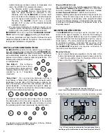
1. Insert a small flat-head screwdriver into the slots at the
bottom and twist while applying inward pressure (see Fig.
1; insert the screwdriver closer to the edges of the unit, as
shown in the Fig. 1 "inset" image).
2. Using the rear housing as a mounting template, secure
optimal Gateway locations relative to Expanders and
locks. See WI2092 for complete information.
The "SIGNAL LEVEL" graph displayed on the front
label of the
AL-NSM
Networx Signal Meter indi-
cates the signal strength as measured in "DL-
Windows units"; the
AL-IME2-EXP
will allow itself
to be connected to the Gateway (or another Expand-
er) if the signal is determined to be 37 or greater.
Therefore, the
AL-NSM
should have a signal
strength of 37 or above at the intended Expander
installation location
We recommend obtaining or creating a layout of your
intended system identifying all proposed installation lo-
cations, also noting building construction materials
IMPORTANT:
Be sure to read the "
EXPANDER GROUP"
DIALS
section on page 3
before
powering your Expanders.
The above guidelines and tips should be followed for each
additional Expander added to the system. See next section
for Expander installation configurations.
INSTALLATION CONFIGURATIONS
AL-IME2-EXP
Expanders can be added in any configura-
tion. Provided the above instructions from
EXPANDER LO-
CATION GUIDELINES
are followed, Gateways / Expanders
will automatically determine the optimal routing pathways
between one another, ensuring optimal signal levels. The
following are examples of Expand-
er configurations:
"
Star Pattern
": This configura-
tion could be used to cover an en-
tire building with a single version 2
Gateway located in the center, sur-
rounded by up to 7 Expanders
(maximum).
"
Daisy-Chain
": For covering long distances, such as a
long hallway, a "daisy-chain" configuration connects several
Expanders in series with a 100 foot maximum distance be-
tween the Gateway and the first (and between each subse-
quent) Expander. In this example, the signal is easily ex-
tended over 700 feet in one direction, and provides coverage
for door locks located along this range:
If a wireless lock along the above daisy-chain is unreacha-
ble, Expanders can be moved as required (in the example
below, Expanders
E3
,
E5
and
E6
were relocated to allow
the wireless signal to reach previously inaccessible locks).
The above are just 3 possible scenarios; in theory, endless
installation configurations are possible.
G
E1
E2
E4
E7
E6
E5
E3
G
E3
E2
E6
E1
E4
E5
E7
G
E1
E2
E3
E4
E5
E6
E7
Fig. 1: To separate rear housing from cover
(Inset: Insert flat-head screwdriver closer to the edges of the unit)
(Inset image)
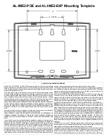
Fig. 2: Rear housing mounting holes for single-gang (A) and
double-gang (B) electrical boxes, and four all-purpose holes (C)
A
B
B
C
C
A
B
B
C
C