background image

24


WIRING DIAGRAM


BT : Boiler Thermostat

F : Fuse
IT : Ignition Transformer
SV : Solenoid Valve
C1 : Contactor

ST : Safety Thermostat

Control Unit : LMO24  255B2 or

            LMO44  255B2 may be used

M

3~

96

95

C1

Air Damper Mo

tor

LKS 160

2

3

1

R
6

Nozzle-2

Burner

SV

SV

IT

2

1

31

F

12

11

10

9

8

7

6

5

4

3

2

1

CONTROL UNIT

Phase

Neutral

Motor
Solenoid Valve

Ignition Transformer

Failure

Photocell

5A

M2 M2

N

L3 L2 L1

S S

BT1 BT1 ST ST BT2 BT2

T1 : Thermal  Relay

T1

SV

3

Содержание CARRIER ALM 125/2

Страница 1: ...ALG SERIES GAS BURNERS ALG 50 2 ALG 70 2 INSTALLATION OPERATION MAINTENANCE ALM SERIES LIGHT OIL BURNERS INSTALLATION ASSEMBLY OPERATION MAINTENANCE...

Страница 2: ...Rev No 0 Book Revision Date 140606 Book Edition Date...

Страница 3: ...OF BURNER TO BOILER 8 PUSHING FORWARD AND PULLING BACK 10 ELECTRODE ADJUSTMENTS 11 COMBUSTION HEAD DIFFUSER ADJUSTMENT 12 COMBUSTION AIRFLOW ADJUSTMENT WITH AIR DAMPER LKS 160 15 AIRFLOW ADJUSTMENT 16...

Страница 4: ...nslated into the official language of the country of destination and take into account the national installation regulations of the country concerned All electrical equipment complies with the require...

Страница 5: ...pipes The best method of carrying the burner is to lift from the bottom of its casing using the combustion head as a point of support When selecting the burner you require please choose a nozzle suite...

Страница 6: ...5 Hinge 6 Burner Motor 7 Fuel Pump 8 1st Nozzle Button 9 Photocell 10 Operation Failure Reset 11 Control Unit 12 Fuse 13 Cable Gland 14 Combustion Head 15 2nd Solenoid Valve 16 Air Damper Motor 17 Sig...

Страница 7: ...ACITY kg h HEAT OUTPUT MOTOR WEIGHT kg POWER SUPPLY kW Kcal h Min Max Min Max Min Max Speed rpm Power kW ALM 125 2 53 4 125 632 8 1482 544 680 1 275 000 2850 2 2 66 3 380 400V 50Hz ALM 174 2 60 5 174...

Страница 8: ...6 1007 895 Y1 X 375 525 398 746 976 152 300 R756 230 45 M N P S M1 Z T Y H J K L D E F G BURNER TYPE B C A Warning The space between boiler door insulation and combustion chamber must be filled with a...

Страница 9: ...n remove the hinge rod 3 and detach boiler connection flange 4 from hinge 2 See figure 4 The boiler connection flange 4 is installed on the boiler 7 with its hinge on the right hand side when viewed f...

Страница 10: ...ee figure 7 PUSHING FORWARD AND PULLING BACK The pulling operation is performed until the burner rest on the hinge protrusion smoothly See figure 8 By this way the burner can be adjusted to a maximum...

Страница 11: ...ing with nozzle selection These burners have the following Advantages 1 The combustion head and diffuser are easily accessible during all service and maintenance operations 2 The nozzle and ignition e...

Страница 12: ...ance between the nozzle tip and diffuser disc top surface and the distance between the combustion head edge and diffuser disc top surface respectively They should be adjusted according to the followin...

Страница 13: ...y Remove the diffuser group 10 of burner See figure 13 from the boiler See figure 14 with the help of the hinges 2 Unscrew the two M6 bolts 11 and remove the combustion head from the boiler connection...

Страница 14: ...ustion head together with the connecting piece again on the diffuser group and check the adjusted distance with calilipers See figure 16 Continue adjusting the combustion head 14 and checking the dist...

Страница 15: ...er via air suction chamber A flap in the air suction chamber adjusts this airflow The air damper actuator in two stage burners operates this air flap The system consists of a 1st stage airflow adjustm...

Страница 16: ...made at the start of combustion airflow trial Check the burner for correct operation at this time The curves below show the air flap adjustment points as a function of boiler capacity ALM 174 2 0 1 2...

Страница 17: ...he following picture shows the suction and return sides of the oil pump where the oil hoses are connected Figure 20 PRINCIPLE OF OPERATION The gear set draws oil from the tank through the built in fil...

Страница 18: ...pump in two pipe lift system with lift height 1 5 m altitude 700 m pipe diameter 8 mm Equivalent lift height 1 5 700 200 1000 2 m Maximum pipe length 13 m Pressure correction only for one pipe system...

Страница 19: ...5 92 79 66 46 53 38 20 54 16 60 31 16 35 18 14 12 4 H m 2 3 1 4 6 d mm 0 0 5 8 7 6 5 4 5 4 8 12 34 14 19 8 48 20 20 11 29 13 15 8 63 26 56 23 10 8 38 33 10 14 5 3 8 8 20 3 30 17 43 5 27 11 9 23 8 10 7...

Страница 20: ...allon per hour at 7 bar and the spray angles are stamped on the nozzles by the manufacturer together with the spray pattern indicated by a symbol See figure 22 SPRAY PATTERN semi solid cone SPRAY ANGL...

Страница 21: ...zles supplied by Steinen Monarch and Hago are best The Steinen nozzles with a spray angle of 60o should be used RECOMMENDED NOZZLES ACCORDING TO BURNER CAPACITY Viscosity 3 4 0 04 cSt Density 0 84 0 0...

Страница 22: ...L SEQUENCE OPERATION AND TIMING tw Waiting time 5 sec t1 Prepurge time 25 sec t1 Purge time 26 sec t3 Pre ignition time 25 sec t3n Post ignition time 5 sec t4 Interval from flame signal to release BV2...

Страница 23: ...the burner can be re activated by pressing the lockout reset button for more than 3 seconds Pressing the reset button again for at least 3 seconds the interface diagnostics will be activated Error cod...

Страница 24: ...t Control Unit LMO24 255B2 or LMO44 255B2 may be used M 3 96 95 C1 Air Damper Motor LKS 160 2 3 1 R 6 Nozzle 2 Burner SV SV IT 2 1 31 F 12 11 10 9 8 7 6 5 4 3 2 1 CONTROL UNIT Phase Neutral Motor Sole...

Страница 25: ...es are easily accessible after the diffuser and electrode group are removed from the boiler with the help of the hinges The nozzle is removed as follows a Unscrew the bolt 1 and take the diffuser grou...

Страница 26: ...26 The control unit contactor fuse and the LED button may easily be reached See figure 5 by removing three M5 bolts on the electric panel cover See figure 6 Figure 5 Figure 6...

Страница 27: ...smoke pipes and combustion chamber during the monthly maintenance Check the condition of boiler combustion chamber once a month and clean at yearly maintenance Have your chimney cleaned and make the...

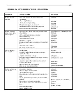
Страница 28: ...Clean g Replace h Replace i Replace Fuel is available but no ignition a Dirty nozzle b Ignition spark or flame fails due to the high velocity of air flow c Ignition transformer is faulty d Loose conne...

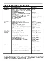
Страница 29: ...k Burner emits an undesirable odor soot or fuel a Fuel leaks from pipes or tank b Dirty or defective nozzle c Insufficient combustion air supply d Poor chimney draught e Accumulation of excessive soot...

Отзывы: