background image

Reversing deflector and operating hydraulics

Repair manual

40

KM/285/EN/1.1.0

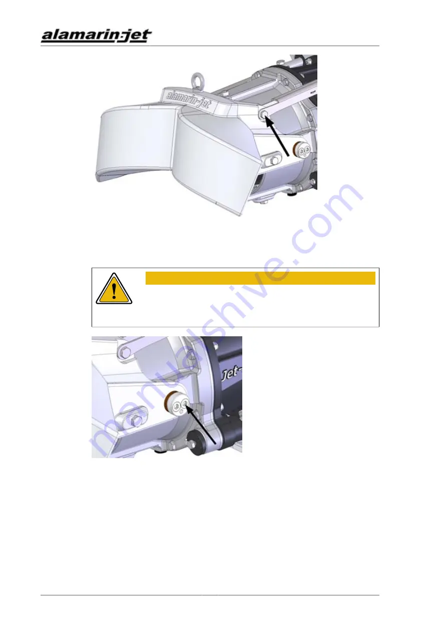
Figure 52. Removing the reversing deflector

2. Open the joint pin screws (2 pcs, figure 53).

WARNING!

Be careful not to drop the deflector.

The deflector weighs approximately 16 kg.

Figure 53. Joint pin screws

3. If you need to replace the plastic bearings on the joint pins, they can be

removed with a suitable mandrel.

The plastic bearings are pushed to their place and can be removed by

pushing (figure 54).

Содержание AJ 285

Страница 1: ...Repair manual ...

Страница 2: ......

Страница 3: ...moving the reversing deflector 39 4 1 2 Repairing the reversing deflector 41 4 1 3 Installing the reversing deflector 41 4 2 Operating hydraulics 42 4 2 1 Removing the cylinder 42 4 2 2 Repairing the cylinder 45 4 2 3 Installing the cylinder 46 4 2 4 Cylinder adjustment 50 4 3 Hydraulic pump 53 4 3 1 Removing the hydraulic pump 53 4 3 2 Repairing the hydraulic pump 54 4 3 3 Installing the hydrauli...

Страница 4: ...ing time expenses of unauthorized repair work of Alamarin Jet products expenses caused by failure of the jet to other components inside or outside the vessel damages to any third parties injuries or any other inconveniences In order for warranty decision Alamarin Jet must receive defected parts with comprehensive failure description attached and transportation charges covered by the purchaser to A...

Страница 5: ...o change without notice Alamarin Jet Oy reserves the right to modify the contents without notice 1 1 Safety precautions Read these instructions carefully before carrying out any procedures Always follow these instructions and the safety precautions shown below Only a person with adequate training is allowed to carry out the procedures described in this manual The person carrying out the procedures...

Страница 6: ...t facilitates the performance of work or a procedure MAINTENANCE ON LAND The boat must be lifted out of the water for maintenance MAINTENANCE IN WATER The maintenance procedure can be carried out in water CARRIED OUT BY ONE PERSON One person can carry out the procedure CARRIED OUT BY TWO PERSONS Two persons must carry out the procedure INDICATOR ARROW ARROW DESCRIBING MOTION Please note that this ...

Страница 7: ...ted at both ends with bearings At the front end of the shaft is a drive flange figure 1 point B to which the intermediate shaft is connected The shaft is also equipped with an impeller figure 1 point C connected with a parallel key The impeller generates pressure as it rotates Figure 1 Main shaft and bearing The front end has a double cone angular contact ball bearing receiving axial thrust and ra...

Страница 8: ...ontainer into which you can drain the old oil from the system Front bearing disassembly 1 Detach the lubricating oil reservoir connectors off of the bearing housing figure 2 and drain the oil from the system Drain the oil from the ends of the hoses into a suitable container Depending on the length of the hoses the oil reservoir and hoses contain approximately 1 to 2 litres of oil Figure 2 Lubricat...

Страница 9: ... tool available that covers and protects the end of the shaft when an extraction tool is used There is also an extraction tool available as an accessory that is specifically designed for removing the drive flange The use of these tools is recommended in order to prevent damage to the end of the shaft The product code of the extraction tool is 11039 while the product code of the shaft s protective ...

Страница 10: ...ger screws or threaded rods and tighten them until they bottom out Tighten them evenly until the bearing housing comes loose from the frame The bearing housing comes loose together with the shaft bearings and the mechanical seal 7 Open the bearing housing cover screws 2 pcs figure 4 point C and remove the bearing housing cover figure 5 point A 8 Remove the drive flange shaft seal figure 5 point B ...

Страница 11: ...e 6 Shaft nut 10 Remove the shaft nut and lock washer figure 7 points A and B 11 Pull the bearing housing off the shaft figure 7 point C The bearing housing comes off together with the bearings and the mechanical seal s static slip ring figure 9 point B Figure 7 Removing the bearing from the shaft 12 Remove the bearings from the bearing housing by pressing them from the impeller side in accordance...

Страница 12: ...ring C Rotating slip ring D Spring for pressing the sealing faces against each other E Rubber bellows F Sealing support ring The slip surfaces are of silicon carbide which is an extremely durable material In order to achieve a high level of sealing the surfaces must be perfectly smooth If the slip surfaces show signs of mechanical damage the seal must be replaced The water on the outside and the o...

Страница 13: ...al seal and the joint surface of the slip ring This is a sign of water in the bearing housing This is completely normal and will not cause any problems When the shaft rotates the oil circulates through the oil reservoir and the water gathers at the bottom of the reservoir Shaft seals A shaft seal that seals the front end of the bearing housing is attached to the bearing housing cover The seal lip ...

Страница 14: ...g Under normal circumstances the operating life of the front bearing is thousands of driving hours However if the lubrication weakens due to for example the failure of the seal or dirty oil the operating life of the bearing will decrease rapidly Using a worn rear bearing also shortens the life span of the front bearing A worn bearing will make noise and may cause the bearing housing to overheat Th...

Страница 15: ...igure 13 Figure 13 Measuring the straightness of the shaft A Supporting point 1 B Supporting point 2 C Measuring point The maximum permissible deviation measured from the surface of the shaft is 0 15 mm in which case the dislocation of the centre line is 0 075 mm NOTE Measure the straightness carefully Excessive deviation in the straightness will cause several problems the most significant being t...

Страница 16: ...ot move on the shaft surface if it is not lubricated CAUTION Only special lubricating gel that vaporises between the rubber and shaft may be used for the lubrication If the lubricant used for the rubber bellows contains oil the bellows might rub against the shaft surface and thereby cause insufficient sealing If the gel is not available the bellows may be lubricated with a small amount of water Th...

Страница 17: ...hten the nut by first tightening it against the bearings by hand and then use a shaft nut wrench to tighten it enough to make one of the teeth of the lock washer connect with the groove in the nut Finish by turning the tooth of the lock washer into the shaft nut groove figure 16 point A Figure 16 Pushing the bearings onto the shaft A Shaft nut E O ring between the bearing housing and the bearing h...

Страница 18: ...ft seal figure 18 point B into the bearing housing cover making sure that it is correctly oriented Make sure that the shaft seal is installed in the correct way figure 19 6 Place the retainer ring figure 18 point A into to the groove on the inner rim of the bearing housing cover figure 18 point C Figure 18 Installing the shaft seal in the bearing housing cover ...

Страница 19: ...sures that the screw holes are aligned figure 20 point B 8 Fasten the bearing housing cover with two M6 screws to a tightness of 9 Nm figure 20 point A Figure 20 Installing the bearing housing cover 9 Replace the seal in the rear section of the drive flange This seal does not necessarily wear since it is static but when the bearing housing is opened it is a good idea to replace it Ensure that the ...

Страница 20: ... clear the key The tightening torque of the drive flange nut figure 22 point A is 150 Nm Use a thread locking compound such as Loctite 242 Figure 22 Installing the drive flange It is recommended to check the tightness of the bearing housing during this phase Attach a piece of hose turned upwards to the OUT connector figure 23 to prevent overflow Fill the bearing housing by adding recommended oil t...

Страница 21: ...il is indicated in red 2 1 4 Installing the front bearing Assemble the front bearing before installing section 2 1 3 Assembly of the front bearing page 11 Front bearing installation 1 Clean the part of the jet s frame where the bearing housing is to be installed The installation surface must be free of any old sealing compound or other impurities and be straight ...

Страница 22: ... into place through the hole in the jet s frame figure 26 point A and tighten the bearing housing fastening screws 6 pcs figure 26 point B through the holes in the drive flange using a long Allen wrench figure 26 point C Use a thread locking compound such as Loctite 242 The tightening torque of the screws is 46 Nm Figure 26 Attaching the bearing housing 4 Install the impeller section 3 4 Installin...

Страница 23: ... hydraulic pump section 4 3 3 Installing the hydraulic pump page 56 2 2 Rear end bearing 2 2 1 Disassembling the rear end bearing Rear end bearing disassembly 1 Remove the stator section 6 1 Removing the stator page 65 2 The rear bearing housing is attached to the stator with three screws figure 27 Undo the screws and remove the plastic cover Figure 27 Rear bearing housing screws 3 Screw one or if...

Страница 24: ...ng to the load on the jet CAUTION If the seals are worn they may allow water to flow into the bearing housing in turn weakening the lubrication of the bearing and shortening its operating life However it is normal for a small amount of water to leak into the bearing housing during operation even if the seals are intact This can be observed as a change in lubricant colour and it does not affect the...

Страница 25: ...the bearing out of the housing from the front side There are holes on the housing race figure 30 to allow pushing the bearing with a mandrel for example Figure 30 Recess allowing for easy removal of the bearing Shaft sleeve There is a sleeve at the rear end of the shaft figure 31 point A that keeps the impeller in place A worn sleeve can be replaced At the end of the shaft there is a locking plate...

Страница 26: ...n the screw at the end of the shaft and pull the sleeve off the shaft 2 2 3 Assembling the rear end bearing Assembly of the rear bearing 1 Push the bearing into the bearing housing from the back figure 32 Use a bearing retaining compound to ensure that the bearing stays in place such as Loctite 648 or similar ...

Страница 27: ...rom the front of the bearing housing The second seal is attached to the plastic cover Ensure that the seals are inserted in the correct way figure 33 Figure 33 Installation direction of the seals 2 2 4 Installing the rear end bearing Before installation ensure that the bearing housing hole in the stator is clean and intact ...

Страница 28: ...ator figure 35 point E of old grease Figure 35 Installing the bearing housing cover 3 Push the bearing housing figure 35 point C into the stator hole figure 35 point D in the correct position so that the three fastening screw figure 35 point A holes are aligned This is when the housing is in the correct position 4 Install the cover figure 35 point B in place and tighten the fastening screws Apply ...

Страница 29: ... stator section 6 3 Installing the stator page 69 2 3 Intermediate shaft The intermediate shaft is the transmission shaft between the motor and jet Usually the intermediate shaft has been acquired and installed by the boat manufacturer The most common types of intermediate shaft are the constant speed shaft and the cardan shaft In addition various flexible shaft couplings are used The intermediate...

Страница 30: ...Main shaft and bearing Repair manual 26 KM 285 EN 1 1 0 ...

Страница 31: ...nt C The torque is transmitted to the shaft using a key The impeller is held in place by a sleeve figure 37 point D attached to the rear end of the shat with a screw The impeller is located in the cone duct which allows the gap between the blade and the duct wall to be quite small There are rings of various thicknesses figure 38 point A on the front side of the impeller These define the location o...

Страница 32: ... vary according to the diameter and length of the blades The impeller type that is used varies according to the situation because the AJ 285 can be attached to various types of motors Therefore each impeller must be type marked The type marking has been punched into the rear of the impeller hub figure 39 The type of the impeller must be declared for example when ordering a new impeller The format ...

Страница 33: ...e impeller easier 3 Pull back the impeller off of the shaft and remove the key from the keyway 3 3 Repairing the impeller Minor damages on the impeller can be repaired Examples of this are dents to the front edge that can be ground out and slightly bent blades that can be hammered back into their original position NOTE The impeller must be balanced after any repair operations If the diameter of th...

Страница 34: ...re fitted in the same way Installing the impeller 1 If the impeller mounting flange was detached from the impeller re attach it 2 Lubricate the flange seals with waterproof petroleum jelly such as Shell Gadus S2 V220AC or similar and push the sleeve into place Note the position of the keyway which is indicated on the impeller hub figure 41 Apply thread locking compound such as Loctite 242 to the s...

Страница 35: ... impeller is transmitted through the adjuster sleeve to the shaft figure 42 point A The sleeve consists of rings of different thickness The length of the sleeve can be adjusted in 0 5 mm approx 0 02 increments by changing the number of the rings This way the impeller gap on the outer race becomes fit ...

Страница 36: ...not reach the shim rings add more shim rings The optimal gap is 0 8 1 2 mm approx 0 031 0 047 at the upper part of the duct When you measure the gap note that the shaft is not centred when the stator is removed but the shaft s rear end hangs low and the whole gap is visible in the upper part of the duct CAUTION If the gap is too big it will cause loss of power and reduce performance 6 Once you hav...

Страница 37: ...d the shaft sleeve figure 44 When installing a new impeller with a larger diameter shim rings are moved from the back of the impeller to the front figure 45 Figure 44 The impeller moves forward wearing gap needs to be reduced Figure 45 The impeller moves backward new impeller gap needs to increased 7 Lubricate the the inner surface of the sleeve to be placed at the end of the shaft with waterproof...

Страница 38: ...he sleeve 1 Once the sleeve is correctly positioned place the locking plate to the end of the shaft and tighten the rear screw to a torque of 46 Nm Apply thread locking compound such as Loctite 242 to the screw 2 Make sure that the impeller cannot move forwards of backwards from its place 3 5 Impeller tunnel The impeller spins inside a tunnel with an aluminium exterior surface figure 47 point A an...

Страница 39: ...the stator section 6 1 Removing the stator page 65 and the the impeller section 3 2 Removing the Impeller page 29 1 Open the connection to the raw water line at the pipe end on the engine room side figure 48 point A 2 Screw the raw water pipe to disconnect it from the rear end figure 48 point B However you can leave it attached to the frame ...

Страница 40: ...e 49 Removing the impeller tunnel from the frame Installing the impeller tunnel 1 Ensure that the o ring between the impeller tunnel and frame is in place Apply waterproof petroleum jelly onto the connecting surface such as Shell Gadus S2 V220AC or similar figure 50 point A 2 Ensure that the set screws 8 pcs are in their correct places in the frame If they have come loose they must be reinstalled ...

Страница 41: ... 37 3 Ensure that the dowel pins of the impeller tunnel are in place figure 50 point C 4 Press the impeller tunnel into place 5 Tighten the nuts and the washers 8 pcs into place to a torque of 46 Nm Figure 50 Installing the impeller tunnel ...

Страница 42: ...Impeller Repair manual 38 KM 285 EN 1 1 0 ...

Страница 43: ...eflector can be lowered even at full speed The reversing deflector is used through a hydraulic cylinder controlled mechanically figure 51 point B A cable runs from the handle in the cabin to the operating lever of the cylinder figure 51 point C The hydraulic cylinder receives its power from a pump integrated in the jet figure 51 point D rotated from the coupling flange with a V belt Figure 51 Reve...

Страница 44: ...nt pin screws 2 pcs figure 53 WARNING Be careful not to drop the deflector The deflector weighs approximately 16 kg Figure 53 Joint pin screws 3 If you need to replace the plastic bearings on the joint pins they can be removed with a suitable mandrel The plastic bearings are pushed to their place and can be removed by pushing figure 54 ...

Страница 45: ...essary The greatest permissible radial clearance is 1 mm The reversing deflector is cast aluminium AlSi7Mg and minor breakages can be repaired by welding The filler metal for the welding is AlMg5 If the arms show breakages the deflector must be replaced not repaired NOTE Bare aluminium areas must be painted when welding the deflector Use paints suitable for aluminium Check the correct paint type f...

Страница 46: ...ector in place and push the joint pins in the holes 3 Tighten the fastening screws 2 on each side figure 56 Figure 56 Attaching the joint pins 4 Attach the joint screw of the hydraulic cylinder intermediate bar figure 52 point A Please note that there must be a sleeve in the reversing deflector s hole 4 2 Operating hydraulics 4 2 1 Removing the cylinder ...

Страница 47: ...lso put plugs at the ends of the hoses Removing the cylinder 1 Remove the cable from the cylinder 1 1 Remove the cable angle joint figure 57 point A from the control lever Figure 57 Removing the cable 1 2 Remove the saddle mounting from the cable bracket figure 57 point B 2 Remove the cylinder pressure hose figure 58 point A and return hose figure 58 point B from the valve and drain the oil into a...

Страница 48: ...ermediate bar between the hydraulic cylinder and the reversing deflector figure 59 point A Figure 59 Removing the cylinder 4 Open the fastening nut of the hydraulic cylinder figure 59 point B If you cannot open the nut with conventional tools you can use special tool 10718 5 Unscrew the cylinder from the jet s frame towards the engine room ...

Страница 49: ...tenance and repair operations of the cylinder The cylinder rear end seal figure 61 point A is a wearing part and must be replaced regularly The replacement can be performed with the cylinder in place The seal sleeve must be replaced as an assembly as disconnecting the seal damages the seal groove The sleeve is also subjected to wear when the cylinder is operated The code for the seal sleeve kit is...

Страница 50: ... joint screw if the cylinder is installed in place figure 61 point B 4 2 3 Installing the cylinder The cylinder is installed in the reverse order to which it was removed 1 Clean the cylinder attachment hole and thread in the frame figure 62 point A 2 Screw the locking nut on to the thread at the end of the cylinder in the correct position figure 62 point B 3 Screw the cylinder onto the threads in ...

Страница 51: ...Reversing deflector and operating hydraulics Repair manual KM 285 EN 1 1 0 47 Figure 62 Installing the cylinder ...

Страница 52: ...63 Cylinder dimensions 4 When the correct measurement X 31 mm is met figure 63 apply some sealing compound such as Sikaflex 291i to the thread and tighten the nut You can turn the cylinder slightly if you want the cable clamp to point directly in the cable s direction of entry figure 64 ...

Страница 53: ...Adjusting the cylinder s position If the nut cannot be tightened with a normal wrench special tool 10718 is available 5 Install the intermediate bar between the cylinder and the deflector Check the correct alignment of the bar figure 65 Figure 65 Installing the cylinder s intermediate bar ...

Страница 54: ... the engine and put it into forward gear the oil is transferred from the reservoir into the system and the pump automatically removes air from the system If the oil level decreases in the reservoir add some oil through the oil reservoir cap There is a dipstick in the reservoir that you can use to check the oil level figure 66 Occasionally move the hydraulic cylinder s operating lever back and fort...

Страница 55: ...ting the cylinder 1 Detach the control cable from the end of the cylinder operating lever figure 68 point A Figure 68 Removing the control cable 2 Loosen the operating lever screw figure 68 point B but do not pull the lever off the shaft yet 3 Place the lever against the limiter on the shaft figure 69 point A ...

Страница 56: ...f its movement range If this happens turn the shaft back slightly 6 Attach the operating lever to the shaft with a screw and tighten the screw The tightening torque is 10 Nm Do not tighten the screw too much 7 Attach the control cable to the screw at the end of the operating lever figure 68 point A 8 Use the control system in the cabin to check that the deflector can move to the up and down positi...

Страница 57: ...ry to completely drain the system you can also put plugs at the ends of the hoses Removing the hydraulic pump 1 Remove the hydraulic pump pressure hose figure 72 point A and suction hose figure 72 point B and drain the oil into a container Alternatively you can plug the ends of the hoses Figure 72 Hoses of the hydraulic pump 2 Remove the hydraulic pump bracket by opening its fastening screws The b...

Страница 58: ...s figure 74 Figure 74 Hydraulic pump fastening screws 4 3 2 Repairing the hydraulic pump A worn belt pulley in the hydraulic pump can be replaced It can also be replaced with the pump attached to the bracket The pump s pressure relief valve may get clogged up with debris which may cause the pump to malfunction The pressure relief valve can be checked and cleaned even when the pump is attached to i...

Страница 59: ...pulley 4 Fit in the new belt pulley 5 Tighten the screws The tightening torque is 23 Nm Use thread locking compound Pressure relief valve disassembly Reserve a container for this procedure into which you can drain the oil from the partially dissembled system 1 Open the cylinder side end of the pressure hose and disconnect the pressure hose from the pump If the pump side end of the hose is equipped...

Страница 60: ...pressure relief valve 4 Set the cleaned pressure relief valve back in the pump 5 Tighten the adapter nut The tightening torque is 40 Nm 4 3 3 Installing the hydraulic pump Installing the hydraulic pump 1 Mount the hydraulic pump in the bracket using fastening screws figure 74 The tightening torque is 23 Nm Use thread locking compound 2 Set the bracket against the front surface of the bearing housi...

Страница 61: ...n hose figure 72 point B 6 Fill the oil reservoir with oil and use the system motor running in forward gear moving the reversing deflector up and down several times This removes air from the system 4 3 4 Replacing the oil filter The oil filter in the oil reservoir must be replaced after every 500 operating hours Replacing the oil filter 1 Open the six cover screws figure 78 Figure 78 Oil reservoir...

Страница 62: ...is not necessary to replace the spring unless it is damaged 3 Put the cover back into place Make sure that the cover seal is correctly positioned in the groove figure 80 point A The cover must also be positioned correctly so that the spring is in line with its support figure 80 point B Figure 80 Oil reservoir cover 4 Reattach the six cover screws figure 78 ...

Страница 63: ...s turned with a hydraulic cylinder figure 81 point B Figure 81 Steering nozzle and actuating cylinder 5 1 Steering nozzle The steering nozzle can also be removed when the boat is in water but it is easier if the boat is out of the water 5 1 1 Removing the steering nozzle 1 Open the connection of the reversing deflector intermediate bar figure 82 and lower the deflector Please note that the steerin...

Страница 64: ... KM 285 EN 1 1 0 Figure 82 Reversing deflector intermediate bar connection 2 Detach the steering cylinder connection from the steering nozzle figure 83 point A 3 Open the steering nozzle joint screws figure 83 point B Figure 83 Removing the steering nozzle ...

Страница 65: ...paired NOTE Bare aluminium areas must be painted when welding the steering nozzle Use paints suitable for aluminium Check the correct paint type from the paint supplier 5 1 3 Installing the steering nozzle 1 Make sure that the steering nozzle joint pivot washer figure 84 point A and locking screw figure 84 point B are in place 2 Place the steering nozzle between the stator joint holes and set the ...

Страница 66: ...ad locking compound such as Loctite 242 and tighten the screw to a torque of 65 Nm 7 Attach the connection of the reversing deflector intermediate bar figure 82 5 2 Steering cylinder 5 2 1 Removing the control cylinder 1 Remove the hydraulic hoses from the cylinder figure 85 point A Figure 85 Cylinder hydraulic hoses 2 Remove the connection between the steering cylinder intermediate bar and piston...

Страница 67: ...rn or damaged parts of the cylinder can be replaced The product code for the sealing kit is P9908 NOTE Only a person with appropriate training is allowed to open the cylinder or carry out the maintenance and repair operations of the cylinder The cylinder rear end seal figure 61 point A is a wearing part and must be replaced regularly The replacement can be performed with the cylinder in place The ...

Страница 68: ... 1 0 Replacement is described in section 4 2 2 Repairing the cylinder page 45 5 2 3 Installing the control cylinder The control cylinder is installed in the same way as the reversing deflector cylinder This is described in section 4 2 3 Installing the cylinder page 46 ...

Страница 69: ...time Be sure to always first disconnect the lubrication hose from the stator angle fitting figure 87 Figure 87 Disconnecting the lubrication hose Detachment one part at a time 1 Remove the reversing deflector and the steering nozzle sections 4 1 1 Removing the reversing deflector page 39 and 5 1 1 Removing the steering nozzle page 59 2 Open the stator fastening screws 8 pcs figure 88 ...

Страница 70: ...mpeller tunnel figure 89 There is a groove in the seal between the parts for inserting the screwdriver Figure 89 Removing the stator Removing the stator as a complete unit 1 Remove the joint between the reversing deflector and the hydraulic cylinder figure 82 as well as the joint between the steering nozzle and the steering cylinder figure 83 point A 2 Open the stator fastening screws 8 pcs figure...

Страница 71: ...versing deflector out as a single assembly figure 90 Figure 90 Removing the stator as a complete unit 6 2 Repairing the stator Replaceable parts in the stator include seals figure 91 points A and B seal B is between the choker and the stator choker figure 91 point C anodes figure 91 points D and E steering nozzle plastic bearings figure 91 point F ...

Страница 72: ...ges can be repaired by welding The filler metal for the welding is AlMg5 Typically the tips of the blades suffer most damages in the stator figure 92 These kinds of damage can be prevented by repair painting any minor damage If the steering nozzle pivots show breakages the part must be replaced not repaired Figure 92 Stator blades ...

Страница 73: ...ng screws 6 pcs 2 Pull the choker off 3 Remove the old seal figure 93 Figure 93 Choker seal 4 Place the new seal in the groove with waterproof petroleum jelly such as Shell Gadus S2 V220AC 5 Fasten the choker back into place The tightening torque of the fastening screws is 10 Nm Use a thread locking compound such as Loctite 242 for the fastening 6 3 Installing the stator 1 Ensure that the stator s...

Страница 74: ... shaft and push the stator into place so that the shaft end enters the rear bearing housing and the dowel pins enter the holes that are intended for them 3 Tighten the screws evenly to a torque of 46 Nm 4 Finish the installation by connecting the rear bearing lubrication hose to the stator angle fitting ...

Страница 75: ...nd a thickener with EP additives mineral oil as a base oil NLGI class 2 operating temperature range 25 to 130 C 13 266 F continuous operating temperature min 75 C 167 F Recommended grease brands Würth Multi Purpose Grease III FAG Multi2 FAG Load 220 Mobil XHP 222 Neste Allrex EP2 Shell Retinax Grease EP2 A grease that has equivalent properties to those mentioned above can also be used for lubricat...

Страница 76: ...signed to use oil that is specifically intended for automatic transmission systems The oil must meet the following requirements Kinematic viscosity 40 33 36 mm 2 s Kinematic viscosity 100 C 7 1 7 7 mm 2 s Viscosity index min 170 Density 15 C 0 835 0 890 g cm 3 Pour point max 42 Flashpoint min 180 Recommended oil brands Mobil ATF 320 FormulaShell ATF DEXRON III Neste ATF X BP Autran DX III ...

Страница 77: ... torques of the screws Strength grade 8 8 10 9 12 9 Thread Tightening torque Nm M5 5 5 4 8 1 6 9 5 7 M6 9 6 7 14 10 16 12 M8 23 17 34 25 40 30 M10 46 34 67 49 79 58 M12 79 58 115 85 135 100 M16 145 107 215 159 250 184 The tightening torque in pound feet approximate value is marked in the table in parentheses after the corresponding value in Nm A suitable thread locking compound that is good for al...

Страница 78: ...Tightening torques Repair manual 74 KM 285 EN 1 1 0 ...

Отзывы: