


Appendix E. Calibration
akYtec GmbH · Vahrenwalder Str. 269 A · 30179 Hannover · Germany Tel.: +49 (0) 511 16 59 672-0 ·
36
Appendix E. Calibration
E.1 General
If the accuracy of the input or output of the module is no longer in accordance with the
specification, it can be calibrated.
NOTICE
Ensure a reliable power supply to the device during the calibration. If it fails, the
calibration should be repeated.
– Each analog input and output has its own calibration coefficients for each sensor
type.
– The calibration is performed using a reference signal source connected to the device
input or output.
– The calibration coefficients are calculated based of the ratio between the current
input signal and the reference signal and stored in the non-volatile device memory.
– If the calculated coefficients go beyond the permissible limits, a message about the
error cause will be displayed.
E.2 Input
Input signals: 4-20 mA, 0-10 V, 0-4000 ohm
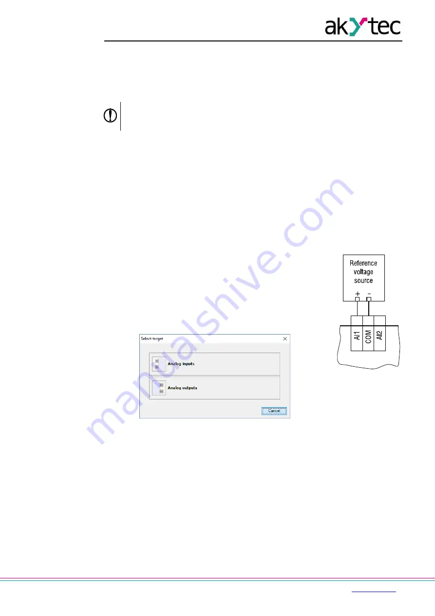
1. Connect the reference signal source of accuracy class at least
0.05 to the input (Fig. E.1).
2. Connect the basic device to the PC.
3. Switch on the device power supply.
4. Start ALP and select the menu item
Device > Calibration
to
start the calibration tool.
5. Select
the device model in the open dialog window.
6. Select
Analog inputs
as calibration target (Fig. E.2).
Fig. E.2
7. Select the type of input signal
and set the other calibration
parameters (Fig. E.3).
o
Set the three points for calibration curve and the filter
time constant.The greater the filter time constant, the
longer the calibration process will take, but the more
precise calibration will be achieved.
o
Select the input to calibrate. If you select
All
, all inputs
will be calibrated sequentially, therefore the appropriate
reference signal has to be applied to all inputs.
Fig. E.1