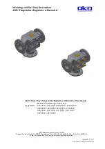
AKO 226.0120 Series Скачать руководство пользователя страница 7

Mounting and Servicing Instructions 
AKO   Temperature Regulator selfactuated 


AKO Regelungstechnik GmbH & Co KG 

Friedrich-Sertürner-Straße 14 • D-51377 Leverkusen • Tel.: +49 (0) 214 / 840599-0 • Fax: +49 (0) 214 / 840599-29 

eMail: [email protected] • Web: http://www.ako-regelungstechnik.de 

7

7. Installation 


7.1 General notes on installation 


If the manufacturer of the aggregate or plant has issued specific installation 

instructions, make sure they are observed. 
The following items should be taken into account besides the general principles 
governing installation work: 


- before installing please make sure that the plant will be pressure less  

              and empty of any medium 
           - in case of high temperatures, please wait for the cooling down to  
 

 ambiance temperature 

          - purge piping system in case of caustic, inflammable, aggressive or 
 

toxic media 


-   Planners/construction companies or operator are responsible for positioning 

and installing products. 

-


For application outside or in adverse environments like corrosion-promoting conditions 
 (sea-water, chemical vapours), special constructions or protective measures 
are recommended. 

-


Before installing the regulating valve, rinse and clean the system otherwise the 
cone/seat area will be damaged and the control hole will be blocked. 

-


The direction of flow must correspond with the arrow on the valve body. 

-


Insert thermometer to control the medium temperature. 

-


Install a strainer upstream of the temperature regulator to prevent that any sealing parts, 
welding spatter and other impurities carried along by the process medium impair the proper 
functioning of the valve, above all the tight shut-off.  
The filter element must be suspended downwards.                                                                                         
 

Note! 

Remember to leave enough space to remove the filter element 


     - The place of installation should be easily accessible and provide ample space for 

  maintenance and extracting  the thermostat out of the piping.  
- Install a shut-off valve upstream and downstream of the temperature regulator to enable 
  repair and maintenance work without emptying the system. 


Note! 

Do not install the temperature regulator between a pressure reducing valve  
and its control line connection 

 
Refer to the data sheet for applications, limits, limits on use and possibilities. 


Содержание 226.0120 Series

Страница 1: ...9 0 Fax 49 0 214 840599 29 eMail info akomail de Web http www ako regelungstechnik de Updated 08 03 2017 Data subject to change without notice AKO Three Way Temperature Regulator with interior Thermos...

Страница 2: ...es on safety information 3 3 Scope of applications 4 4 Operation principles 5 5 Technical data 5 5 1 Regulating Valve 5 5 2 Wax Thermostat 5 5 3 Dimensions 6 5 4 Marking 6 6 Transport and storage 6 7...

Страница 3: ...ing data submitted in the order Note that the manufacturer does not assume any responsibility for damage caused by external forces or any other external influences The manufacturer reserves the right...

Страница 4: ...ats require no auxiliary energy whatsoever Refer to the data sheet for applications limits on use and possibilities Certain media require or preclude the use of special materials The valves are design...

Страница 5: ...the change in temperature of the medium flowing through The descriptions A B and C have been cast on the housing of the thermostat The thermostats can be installed in every position 5 Technical Data...

Страница 6: ...0 226 0120 050 226 0121 050 50 165 102 20 150 135 165 225 125 4x18 1 17 0 17 0 226 0120 065 226 0121 065 65 185 122 20 165 116 146 254 145 4x18 2 25 0 26 0 226 0120 080 226 0121 080 80 200 138 22 171...

Страница 7: ...sea water chemical vapours special constructions or protective measures are recommended Before installing the regulating valve rinse and clean the system otherwise the cone seat area will be damaged a...

Страница 8: ...t during automatic operation If the thermostat fails the control valve can be used as a manually operated three way valve via the emergency manual adjustment and therefore can be set in any position u...

Страница 9: ...erdimensioned recalculate dimensioning of control valve pressure loss of cooler too high reduce pressure difference between port B and C Reasons for control temperature being too low the temperature r...

Страница 10: ...at with different temperature range has been fitted replace the type label by a new one showing the correct 12 3 Testing the function of the manual override open lock nut pos 10 turn the adjustment bo...

Отзывы: