


Pinout Information
Pin Descriptions
PORTA5
202
I/O U5
General-purpose I/O port bit controlled by PADAT5 and PAEN5. This pin
has other possible functions depending on the IREN, EIEN registers.
• When EIEN=1 and PAEN5=1, this pin can function as an external
interrupt to the on-chip CPU.
• When IREN=1 and PAEN5=1, this pin can function as an input to the on-
chip IR receiver 1. (IRRCVR1). .
PORTA6
201
I/O U5
General-purpose I/O port bit controlled by PADAT6 and PAEN6. This pin
can also function as BLKSPL when BLKSMPLEN=1.
• When BLKSMPLEN=1 and PAEN6=0, PORTA6 is GPORT black sample
clamp pulse output (typically used as port of an external DC restoration
circuit) (BLKSPL) This pin has one other possible function when
PREF1EN=1.
• When PREF1EN=1 and PAEN6=0, PORTA6 is a variable duty-cycle
pulse reference generator (PWM) output controlled by PREF1HI and
PREF1LO.
PORTA7
200
I/O D5
General-purpose I/O port bit controlled by PADAT7 and PAEN7. This pin
has one other possible function when PREF0EN=1.
When PREF0EN=1 and PAEN7=0, PORTA7 is a variable duty-cycle pulse
reference generator (PWM) output controlled by PREF0HI and PREF0LO.
PORTB0
57
I/O D5
General purpose I/O port bit controlled by PBDAT0 and PBEN0. PORTB0
can also function as GRO0 when in 48 bit graphics input mode; VR0 when
in 24 bit RGB video input mode; Y0 when in 24 bit YUV video input mode.
PORTB1
58
I/O D5
General purpose I/O port bit controlled by PBDAT1 and PBEN1. PORTB1
can also function as GRO1 when in 48 bit graphics input mode; VR1 when
in 24 bit RGB video input mode; Y1 when in 24 bit YUV video input mode.
PORTB2
59
I/O D5
General purpose I/O port bit controlled by PBDAT2 and PBEN2. PORTB2
can also function as:
PORTB3
60
I/O D5
General purpose I/O port bit controlled by PBDAT3 and PBEN3. PORTB3
can also function as:
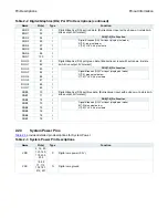
Table 2-6 Peripheral Interface Pin Descriptions (continued)
Name
Pin(s)
Type
Function
Function
When in
DB1E
Dual-pixel 27-bit output mode
DB0
30-bit output mode
GRO2
48-bit graphics input mode
VR2
24-bit RGB video input mode
Y2
24-bit YUV video input mode
Cb0
30-bit YCbCr input mode (CSCD30BIT).
Function
When in
DB1O
Dual-pixel 27-bit output mode
DB1
30-bit output mode
GRO3
48-bit graphics input mode
VR3
24-bit RGB video input mode
Y3
24-bit YUV video input mode
Cb1
30-bit YCbCr input mode (CSCD30BIT).
Содержание LCT2662
Страница 25: ......
Страница 26: ......
Страница 27: ......
Страница 28: ......
Страница 29: ......
Страница 30: ......
Страница 31: ......
Страница 32: ......
Страница 33: ......
Страница 34: ......
Страница 94: ......
Страница 95: ......
Страница 96: ......
Страница 97: ......
Страница 98: ......
Страница 99: ......
Страница 100: ......
Страница 101: ......
Страница 102: ......
Страница 103: ...Input configuration Power amplifier ...
Страница 104: ......
Страница 105: ......
Страница 106: ......
Страница 107: ......
Страница 108: ......
Страница 109: ......
Страница 110: ......
Страница 111: ...Exploded View Diagram Exploded View Diagram ...


