29CTF05BS
3 – 26
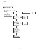
FOCUS ADJUSTMENT
I
D
N
O
C
T
N
E
M
T
S
U
J
D
A
T
N
I
O
P
T
N
E
M
T
S
U
J
D
A
O
N
S
K
R
A
M
E
R
R
O
M
R
O
F
E
V
A
W
E
R
U
D
E
C
O
R
P
/
N
O
I
T
1
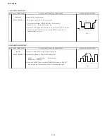
FOCUS
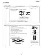
1. Receive E-5CH (Monoscop pattern).
ADJUSTMENT
2. With the remote controller, make the image normal.
3. Adjust the focus VR to make the character "575" on left bottom of monoscope as
fine as possible.
CUT OFF, BKGD, SUB-CONT ADJUSTMENT
I
D
N
O
C
T
N
E
M
T
S
U
J
D
A
T
N
I
O
P
T
N
E
M
T
S
U
J
D
A
O
N
S
K
R
A
M
E
R
R
O
M
R
O
F
E
V
A
W
E
R
U
D
E
C
O
R
P
/
N
O
I
T
1
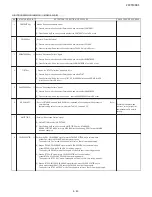
CRT CUTOFF
Note :
ADJUSTMENT
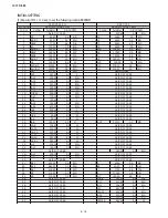
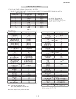
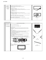
1. Before CRT cutoffadjustment, make sure following items are in INITIAL DATA.
(I2C BUS CONTROL)
a) A020 CUT-RS = 32
b) A021 CUT-GS = 32
c) A109 CUT OFF = 15
(1) Switch TV to video mode , blue back off, with no video signal and press R/C to
set picture into normal condition.
(2) Go to service mode at adjustment mode item A110 (VG2).
(3) Adjust screen voltage until retrace line appear, the following OSD will appear at
bottom of screen.
UNSTABLE
OUT
ABOVE
(4) Finally, slowly decrease the screen variable resistor until following OSD appear.
STABLE
IN
ABOVE / BELOW *
* The last OSD row is the indication of the screen voltage value. Ifi t show "BELOW",
please increase the screen voltage and vice versa until "STABLE" AND "IN" OSD
appear.
Note :
No matter the indication ofl ast row's OSD is indicate "ABOVE" or "BELOW", the
important thing is OSD change to "STABLE" and "IN".
Содержание 29CTF05BS
Страница 1: ...Service manual Colour TV set 29CTF05BS ...
Страница 46: ...29CTF05BS 7 2 ...
Страница 50: ...29CTF05BS 10 2 ...
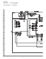
Страница 51: ...29CTF05BS 10 3 2 SCHEMATIC DIAGRAM CRT UNIT 29CTF05BS ...
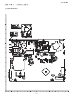
Страница 53: ...29CTF05BS 11 2 2 PWB A MAIN UNIT 1 MAIN UNIT COMPONENT SIDE ...
Страница 54: ...29CTF05BS 11 3 ...
Страница 55: ...29CTF05BS 11 4 2 MAIN UNIT CHIP PARTS SIDE ...
Страница 56: ...29CTF05BS 11 5 ...

