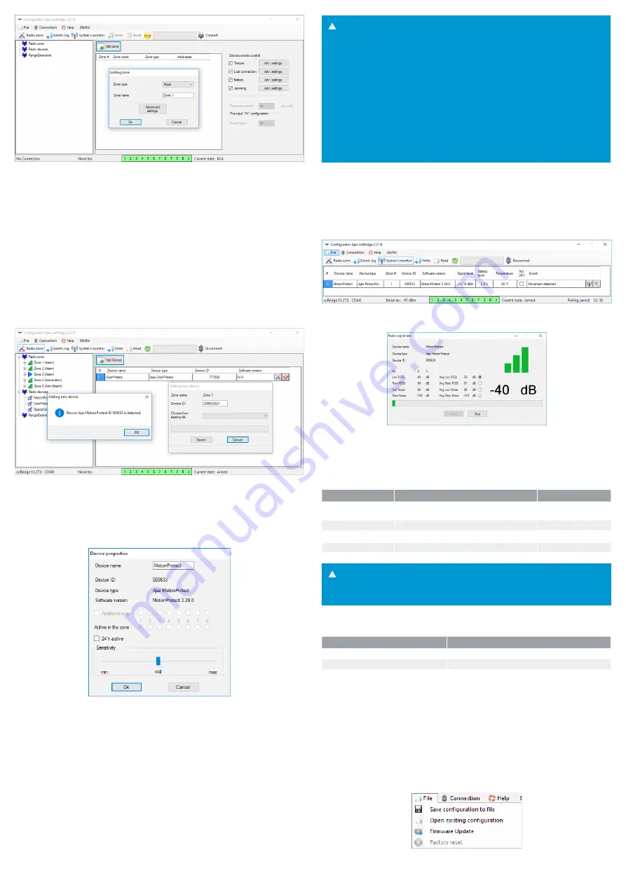
PICTURE 3. Adding a zone
PICTURE 6. “System’s monitor” page
PICTURE 7. Signal level
PICTURE 4. Device registration window
PICTURE 5. The sensor’s properties’ menu makes it possible to
register the sensor in the zone
PICTURE 8. “File” menu
Then, appropriate “Zone type” and settings is to be selected (consult
paragraphs 6.4 and 6.6 of the present manual). To add a device chose
necessary zone and click “Add a device” button. Then, a “Adding new
device” window appears and it is necessary enter sensor’s identifier (ID)
applied on it below QR code, then click the “Search” button (PICTURE 4).
When the search indicator bar begins to move, it is necessary to turn
on the sensor. The registration request is sent only when the sensor is
being switched on! In case of the registration fail, turn off the sensor
for 5 seconds and then turn it on again. If the sensor is on and its light
blinks once per second during one minute, it means that the sensor is not
registered! The light blinks in the same way if the sensor is deleted from
the ocBridge!
Please check the signal level of the connected devices! The radio signal
test you can find on the page “System’s monitor” of the configuration
software. To start radio signal test press the button with antenna against
the selected sensor (PICTURE 6) (only when the sensors are in the
operating mode and there is no red light).
4.3. If the sensor was mistakenly registered in a wrong zone, click on its
“Properties” button. The settings window will appear permitting to select
a new zone for the sensor (PICTURE 5).
The results of the test are shown in the configuration software (PICTURE
7) as 3 indication bars, and by the sensor light. The test results can be the
following:
When an additional wire sensor is connected to the external digital input
of the wireless sensor, in the properties activate the checkbox “Additional
input” (PICTURE 5). If a sensor (for example, a LeaksProtect) is designed
for working 24 h, activate in the checkbox properties “24 h active”. 24 h
sensors and normal sensors should not be placed in the same zone! If
necessary, adjust the sensor’s sensitivity.
4.4 When the sensors are successfully registered in the security system,
click the button “Write” (PICTURE 4) to save sensors’ configuration data
in the ocBridge receiver’s memory. When ocBridge connected to the
PC, click the button “Read” (PICTURE 4) to read the pre-saved sensors’
configuration from the ocBridge memory.
4.5. Select an appropriate place to install the sensors.
4.6.The maximum number of devices that you can connect to the ocBridge
depends on the polling period
5. USING CONFIGURATION SOFTWARE
5.1. “File” menu (PICTURE 8) allows to:
• save active configuration of ocBridge settings in file on PC (Save
configurations to file);
• upload to ocBridge the settings’ configuration saved on the computer
(Open the existing configuration);
• start the firmware upgrade (Firmware update);
• clear all settings (Factory reset). All the data and previously saved
settings will be deleted!
ATTENTION!
Please install the sensors in the places with the signal level of 3 or 2
bars. Otherwise, the sensor may function inconsistently.
RECIEVER
SENSOR'S LIGHT EMITTING DIODE DESCRIPTION
3 indication bars lights permanently, with short breaks
each 1.5 seconds
excellent signal
2 indication bars blinks 5 times per second
medium signal
1 indication bar
blinks twice per second
low signal
no bar
Short flashes each 1.5 seconds
no signal
SENSORS’ QUANTITY
POLLING PERIOD
100
36 seconds and more
79
24 seconds
39
12 seconds
ATTENTION!
Make sure that installation location of sensor, has a stable radio contact
with the ocBridge receiver! A maximum distance of 2000 m (6552 ft)
between the sensor and the receiver is mentioned as a comparison with
other devices. This distance was found is as a result of open area tests.
Connection quality and distance between the sensor and the receiver
can vary depending on installation location, walls, compartments,
bridgings, as well as the thickness and constructional material. The
signal loses a power passing through barriers. For example, distance
between the detector and receiver that divided by two concrete walls
is approximately 30 m (98.4 ft). Take into consideration, if you move the
sensor even 10 cm(4 in), it is possible to improve significantly the quality
radio signal between the sensor and the ocBridge.


